EasyManua.ls Logo

Wittenstein cyber motor simco SIM2002D - Sercos

Default Icon
51 pages
Print Icon
To Next Page IconTo Next Page
To Previous Page IconTo Previous Page
Loading...
Operation Manual simco
®
drive
en-22 4022-D033499 Revision: 11a
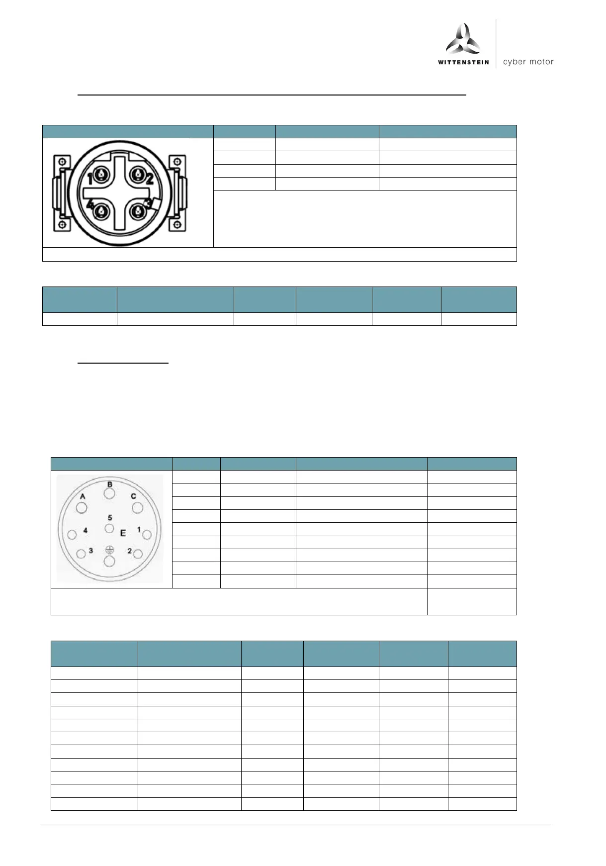
6.3.9 X6/X7: Fieldbus interface EtherCat, PROFINET, EtherNet/IP and SERCOS III
The signals are galvanically isolated from the logic and power of the drive.
Figure
Pin no.
Signal name
Function
1
TD+
Transmit Data +
2
RD+
Receive Data +
3
TD-
Transmit Data -
4
RD-
Receive Data -
Plug type on drive amplifier: M12, 4-pin, female, D-coded at X6 and X7
Connection
Properties
Unit
Minimum
value
Nominal
value
Maximum
value
Transmission speed
MBit/s
100
6.3.10 X8: Power supply
The logic supply (pin 1 + 2) is galvanically isolated from the intermediate voltage
(pin A + B).
The safety input STO is galvanically isolated from the intermediate voltage
(pin A + B).
The intermediate voltage - (pin B) is connected inside the device to the housing as
a functional ground.
Figure
Pin no.
Signal name
Function
Input/output
A
DCBus+
Intermediate voltage +
Input
B
DCBus-
Intermediate voltage -
Input
C
CHOPPER
External brake resistor
Output
FE
FE
Functional earth
Functional earth
1
VCC24
Logic supply + 24 VDC
Input
2
GND
Logic reference ground
Input
3
STO
Safe Torque off input
Input
4
N.C.
5
STO GND
Reference ground STO
Input
Plug type on drive amplifier: Intercontec, itec 915, 9-pin, male
(EEGA 201 NN00 00 0508 000)
Connection
Properties
Unit
Minimum
value
Nominal
value
Maximum
value
DCBus+ / -
Voltage
V DC
16
48
56
Current
A DC
25
Chopper
Voltage
V DC
52
Current
A DC
5
VCC24
Voltage
V DC
22
24
26
Current
mA DC
200
STO
Voltage
V DC
22
24
26
Current
mA DC
80

Table of Contents