EasyManua.ls Logo

Wittenstein cyber motor simco SIM2002D - X7: Motor Connection

Default Icon
51 pages
Print Icon
To Next Page IconTo Next Page
To Previous Page IconTo Previous Page
Loading...
Operation Manual simco
®
drive
en-32 4022-D033499 Revision: 11a
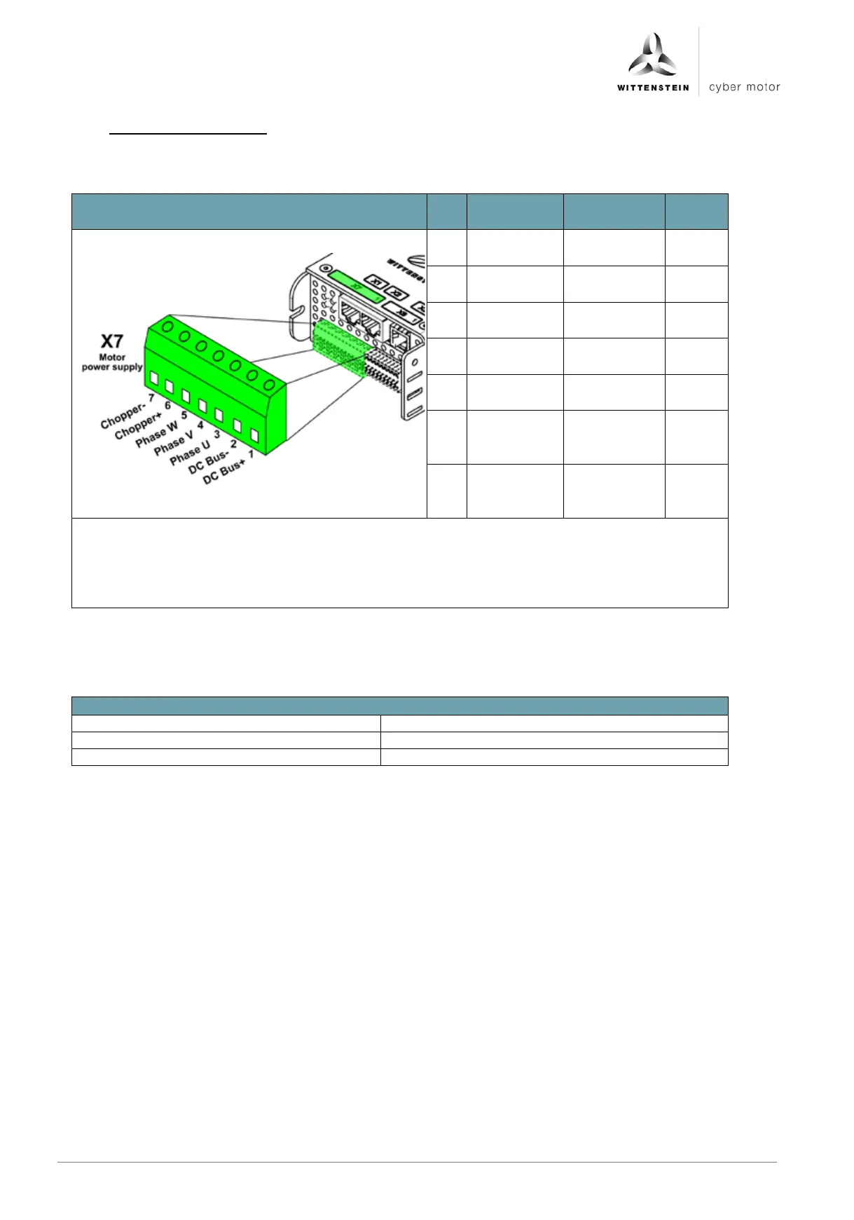
6.4.11 X7: Motor connection
The intermediate voltage - (pin 2) is connected inside the device to the housing as a
functional ground.
Figure
Pin
no.
Signal
name
Function
Input /
output
1
DCBus+
Intermediate
voltage +
Input
2
DCBus-
Intermediate
voltage -
Input
3
PHASE_U
Motor phase
U
Output
4
PHASE_V
Motor phase
V
Output
5
PHASE_W
Motor phase
W
Output
6
Chopper +
External
brake
resistor
7
Chopper -
External
brake
resistor
Plug type at cable: Phoenix Contact MSTBT 2,5 HC/ 7-ST
Permissible conductor cross-section: 0,25 .. 2,5 mm²
Stripping length: 7 mm
Tightening torque: 0,5 .. 0,6 Nm, in order to meet the UL conformity, the tightening
torque must be 0.5 Nm
The following overview shows the correct wiring of the motor phases of the cyber® dynamic line via the
adapter cables S/L-cable xxxHI-xxxx-BA0-6/3:
wiring diagram
U
red
V
white
W
black

Table of Contents