1-S25
L3130 · L3430 · L3830 · L4630 · L5030, WSM
ENGINE
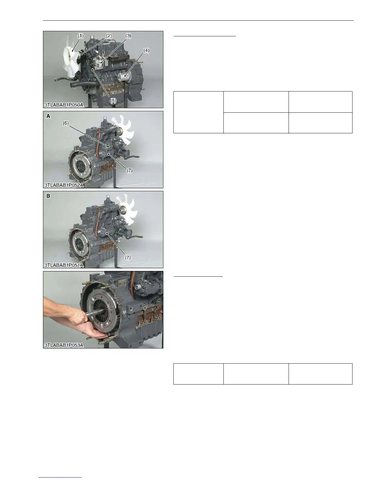
Outer Parts of Engine
1. Remove the hydraulic pump (7) with pump holder and regulating
valve (6).
2. Remove the radiator fan (1), belt and fan pulley (2).
3. Remove the alternator (3).
4. Remove the starter motor (4).
(When reassembling)
• Be sure to adjust the fan belt tension. (Refer to G-23.)
W10169070
Clutch Assembly
1. Remove the clutch from the flywheel.
(When reassembling)
• Direct the shorter end of the clutch disc boss toward the flywheel.
• Apply molybdenum disulphide (Three Bond 1901 or equivalent)
to the splines of clutch disc boss.
• Install the pressure plate, nothing the position of straight pins.
• Align the center of disc and flywheel by inserting the clutch
center tool. (See page G-47.)
• Do not allow grease and oil on the clutch disc facing.
W10171850
Tightening torque
Alternator mounting screw
(M10)
39.2 to 44.1 N·m
4.0 to 4.5 kgf·m
28.9 to 32.5 ft-lbs
Tension adjusting screw
(M8)
17.6 to 20.6 N·m
1.8 to 2.1 kgf·m
13.0 to 15.2 ft-lbs
(1) Radiator Fan
(2) Fan Pulley
(3) Alternator
(4) Starter Motor
(5) Fan Belt
(6) Regulating Valve
(7) Hydraulic Pump
A : Manual Transmission and GST
Model
B : HST Model
Tightening torque Clutch mounting screws
23.5 to 27.5 N·m
2.4 to 2.8 kgf·m
17.5 to 20.3 ft-lbs