3-M28
L3130 · L3430 · L3830 · L4630 · L5030, WSM
TRANSMISSION
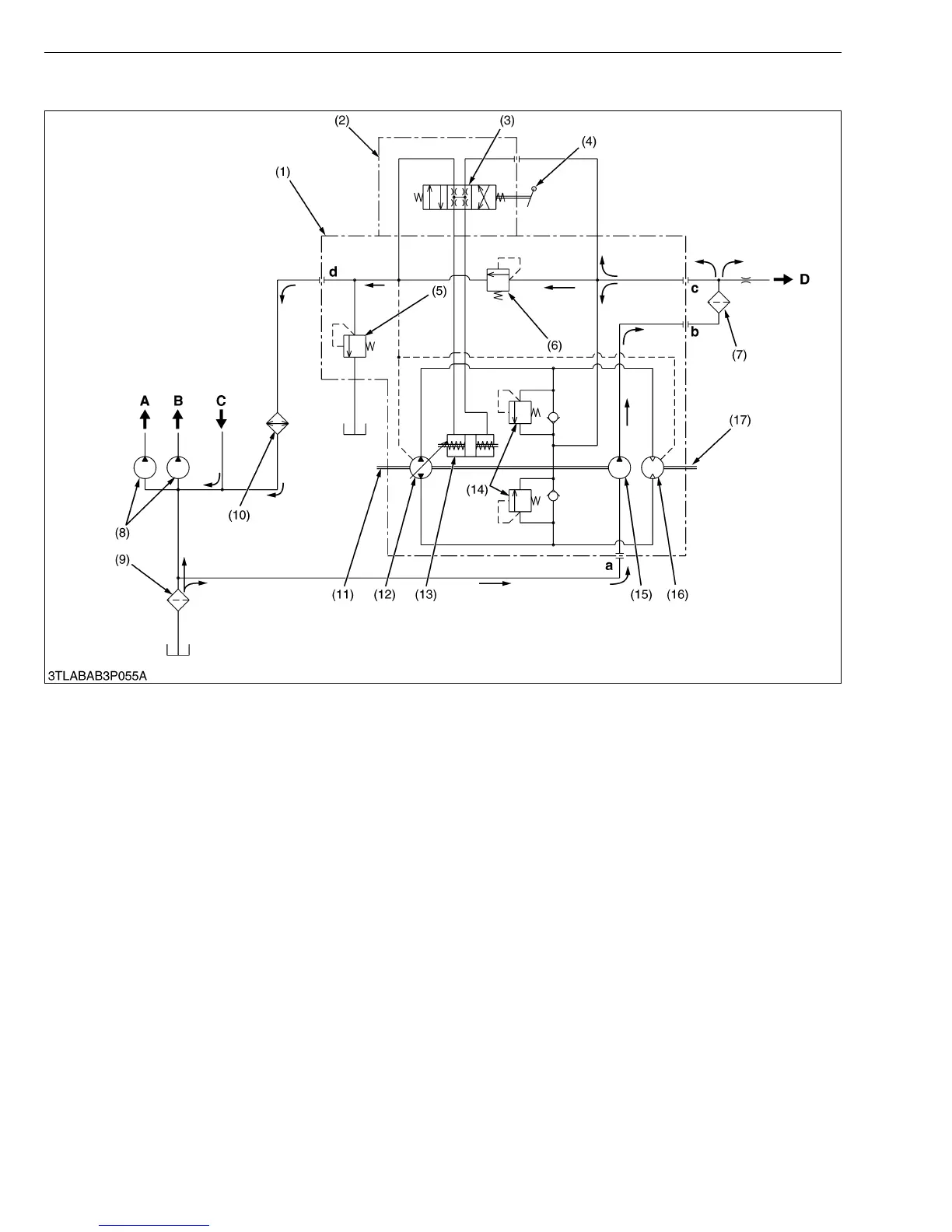
(B) Oil Flow
Oil flows in HST case from a-port, and is sent to b-port with the charge pump (15). Oil from b-port is sent to the
HST circuit and the PTO clutch circuit through the filter (7). Moreover, the oil of the HST circuit sent to c-port is flowed
into the servo regulator (2) and HST main circuit. At this time, the pressure in the regulator, HST main circuit (closed
circuit) and PTO clutch circuit is controlled with the charge relief valve (6). The oil in regulator is used for the
movement of servo piston (13) which is operated by the regulator valve (3) and HST pedal (4). And the oil in the HST
main circuit gets circulated between the variable displacement piston pump (12) and the fixed displacement piston
motor (16), which forms a closed circuit.
On the other hand, surplus oil with the charge relief valve (6) flows out from d-port, and is sent to the suction line
through the oil cooler (10). And the case relief valve (5) controls pressure in the HST case.
(Reference)
• Valve Setting Pressure [Oil temperature : 40 to 60 °C (104 to 140 °F)]
- Charge Relief Valve : 2.25 to 2.45 MPa (23 to 25 kgf/cm
2
, 327 to 355 psi)
- Check and High Pressure Relief Valve : 33.3 to 36.3 MPa (340 to 370 kgf/cm
2
, 4836 to 5262 psi)
- Case Relief Valve : 0.29 MPa (3.0 kgf/cm
2
, 42.7 psi)
(1) HST Assembly
(2) Servo Regulator Assembly
(3) Regulator Valve
(4) Control Lever (HST Pedal)
(5) Case Relief Valve
(6) Charge Relief Valve
(7) Filter
(8) Hydraulic Pump
(9) Filter
(10) Oil Cooler
(11) Input Shaft (Pump Shaft)
(12) Pump Cylinder Block
(13) Servo Piston
(14) Check and High Pressure
Relief Valve
(15) Charge Pump
(16) Motor Cylinder Block
(17) Output Shaft (Motor Shaft)
A : To Hydraulic Block
B : To Steering Controller
C : From Steering Controller
D : To PTO Clutch Valve
a : a-port (In from suction line)
b : b-port (Out by charge pump)
c : c-port (In from charge pump)
d : d-port (Out from HST circuit)