8-S19
L3130 · L3430 · L3830 · L4630 · L5030, WSM
HYDRAULIC SYSTEM
Drawbar Frame and Hydraulic Cylinder
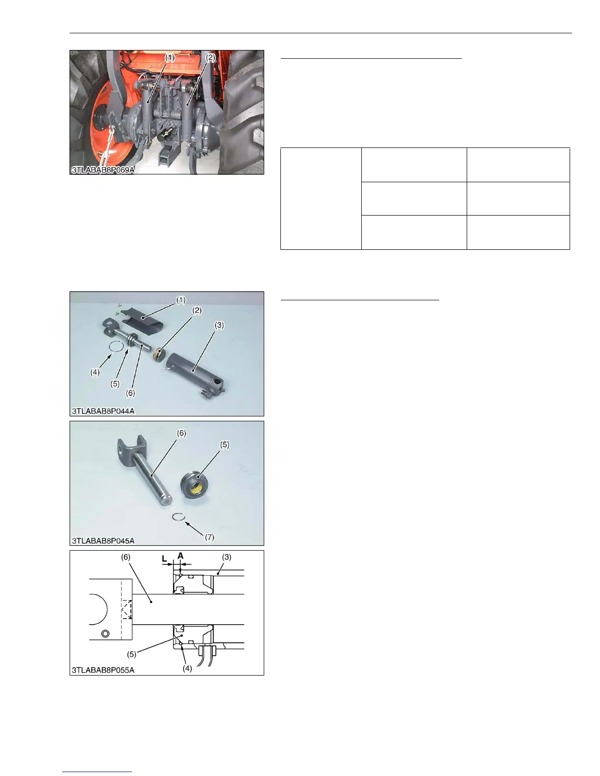
1. Remove the drawbar frame (3).
2. Remove the hydraulic cylinder pins.
3. Disconnect the hydraulic cylinder hoses and return hoses, then
remove the hydraulic cylinders (1), (2).
(When reassembling)
• Apply grease to the hydraulic cylinder pins.
• Install the cylinder pin (lower) from right hand side.
W1018343
Disassembling Hydraulic Cylinder
1. Remove the cylinder cover (1).
2. Remove the liquid gasket from top of head (5).
3. Slightly tap-in the head (5) to inside, and remove the internal
snap ring (4) by using the small screwdriver.
4. If the internal snap ring (4) cannot be removed by above-
mentioned method, remove it by the following procedure.
- Carefully clamp the cylinder tube (3) in a vise.
- Drill approx. 2.5 mm (0.1 in.) diameter hole on the cylinder tube
(position A) just over the internal snap ring (4) as shown in
figure.
- Use a small screwdriver and remove the internal snap ring (4).
Simultaneously support this action by pushing from the outside
of the cylinder tube with another small screwdriver or similar
tool.
5. Draw out the rod (6) and head (5).
6. Inject the compressed air through the oil inlet port of the cylinder
tube (3), and remove the piston (2).
7. Remove the external snap ring (7), and remove the head (5).
(When reassembling)
• Apply transmission fluid to the piston (2), head (5) and cylinder
tube (3).
• Take care not to damage the O-ring, backup ring and seal.
• Apply liquid gasket (Three Bond 1208D or equivalent) to the top
of head (5), while pressing the head (5) against internal snap ring
(4).
• After reassembling the cylinder, be sure to close the drilled hole
by liquid gasket.
W1018811
Tightening torque
Drawbar frame mounting
screw (M14)
166.7 to 196.1 N·m
17.0 to 20.0 kgf·m
123.0 to 144.7 ft-lbs
Drawbar frame mounting
screw (M12)
77.5 to 90.2 N·m
7.9 to 9.2 kgf·m
57.1 to 66.5 ft-lbs
Hydraulic cylinder hose
34.3 to 48.1 N·m
3.5 to 4.9 kgf·m
25.3 to 35.4 ft-lbs
(1) Hydraulic Cylinder LH
(2) Hydraulic Cylinder RH
(3) Drawbar Frame
(1) Cylinder Cover
(2) Piston
(3) Cylinder Tube
(4) Internal Snap Ring
(5) Head
(6) Rod
(7) External Snap Ring
A : Position for drilling
L : 6.0 mm (0.236 in.)