8-S20
L3130 · L3430 · L3830 · L4630 · L5030, WSM
HYDRAULIC SYSTEM
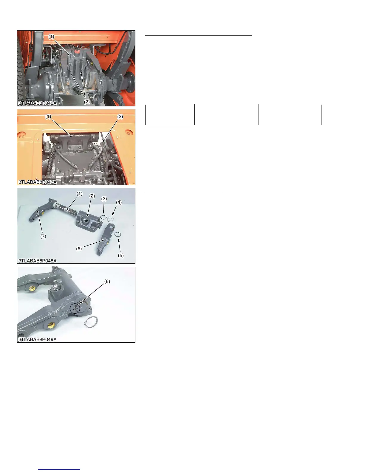
Top Link Holder and Lift Arm Support
1. Disconnect the position control feedback rod (3).
2. Remove the top link holder (2).
3. Remove the lift arm support (1).
(When reassembling)
• Apply liquid gasket (Three Bond 1208D or equivalent) to joint
face of the lift arm support and transmission case after eliminate
the water, oil and stuck liquid gasket.
• After reassembling, be sure to adjust the position control
feedback rod length. (See page 8-S12.)
W1019071
Lift Arm and Lift Arm Shaft
1. Remove the external snap ring (5).
2. Remove the lift arm RH (6).
3. Draw out the lift arm shaft (1) and lift arm LH (7) as a unit.
4. Remove the collar (4) and O-ring (3).
(When reassembling)
• Align the alignment marks (8) of the lift arm shaft and lift arms.
• Apply grease to the right and left bushings of lift arm support and
O-rings.
• Take care not to damage the O-rings.
W1019375
Tightening torque
Top link holder mounting
screw
77.5 to 90.2 N·m
7.9 to 9.2 kgf·m
57.1 to 66.5 ft-lbs
(1) Lift Arm Support
(2) Top Link Holder
(3) Position Control Feedback Rod
(1) Lift Arm Shaft
(2) Lift Arm Support
(3) O-ring
(4) Collar
(5) External Snap Ring
(6) Lift Arm RH
(7) Lift Arm LH
(8) Alignment Mark