9-S28
L3130 · L3430 · L3830 · L4630 · L5030, WSM
ELECTRICAL SYSTEM
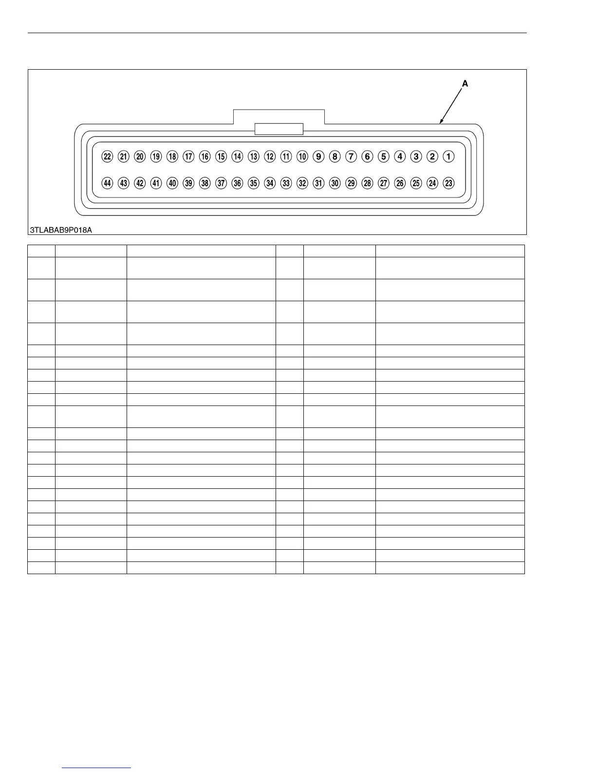
(B) Checking by Electric Control Unit (ECU)
A : ECU Connector of Wire Harness Side
No. Color of wiring Terminal Name No. Color of wiring Terminal Name
1
––23 Green / White
Output terminal for proportional
reducing valve
2 Red / Yellow
Output voltage 12 V
(for pressure switch)
24
––
3 ––25 Brown / Blue
Output terminal for sub-range shift
solenoid
4 Red
Output voltage 12 V
(for Check connector)
26 Brown / Yellow
Output terminal for main range shift
solenoid
5
––27 Brown / Black Output terminal for 1st shift solenoid
6
––28 Brown / White Output terminal for 2nd shift solenoid
7 Black GND (ground for circuit line) 29 Brown / Red Output terminal for 3rd shift solenoid
8 Red / Yellow +12 V (power source from main switch) 30 Brown / Green Output terminal for 4th shift solenoid
9
––31 Red +12 V (power source from battery)
10 Black / White GND (ground for oil temp. sensor) 32 Blue / Red
Return line terminal for proportional
reducing valve
11 Black / White GND (ground for check connector) 33 Black / White GND (ground for sensor)
12
––34 Red / White +5 V (power source for sensor)
13
––35 Yellow / White Pressure switch
14 Black / Yellow Shuttle switch (Neutral) 36 Yellow / Orange Shuttle switch (Forward)
15
––37 Red / Green Shuttle switch (Reverse)
16
––38 ––
17 Orange Traveling speed sensor 39 Light green Engine tachometer sensor
18
––40 ––
19 White / Yellow Oil temperature sensor 41 ––
20 ––42 White / Green GST lever sensor
21 Brown / White RS485 (–) 43 Brown RS485 (+)
22 Pink TXD (for check connector) 44 Violet RXD (for check connector)



 To Next Page