9-S29
L3130 · L3430 · L3830 · L4630 · L5030, WSM
ELECTRICAL SYSTEM
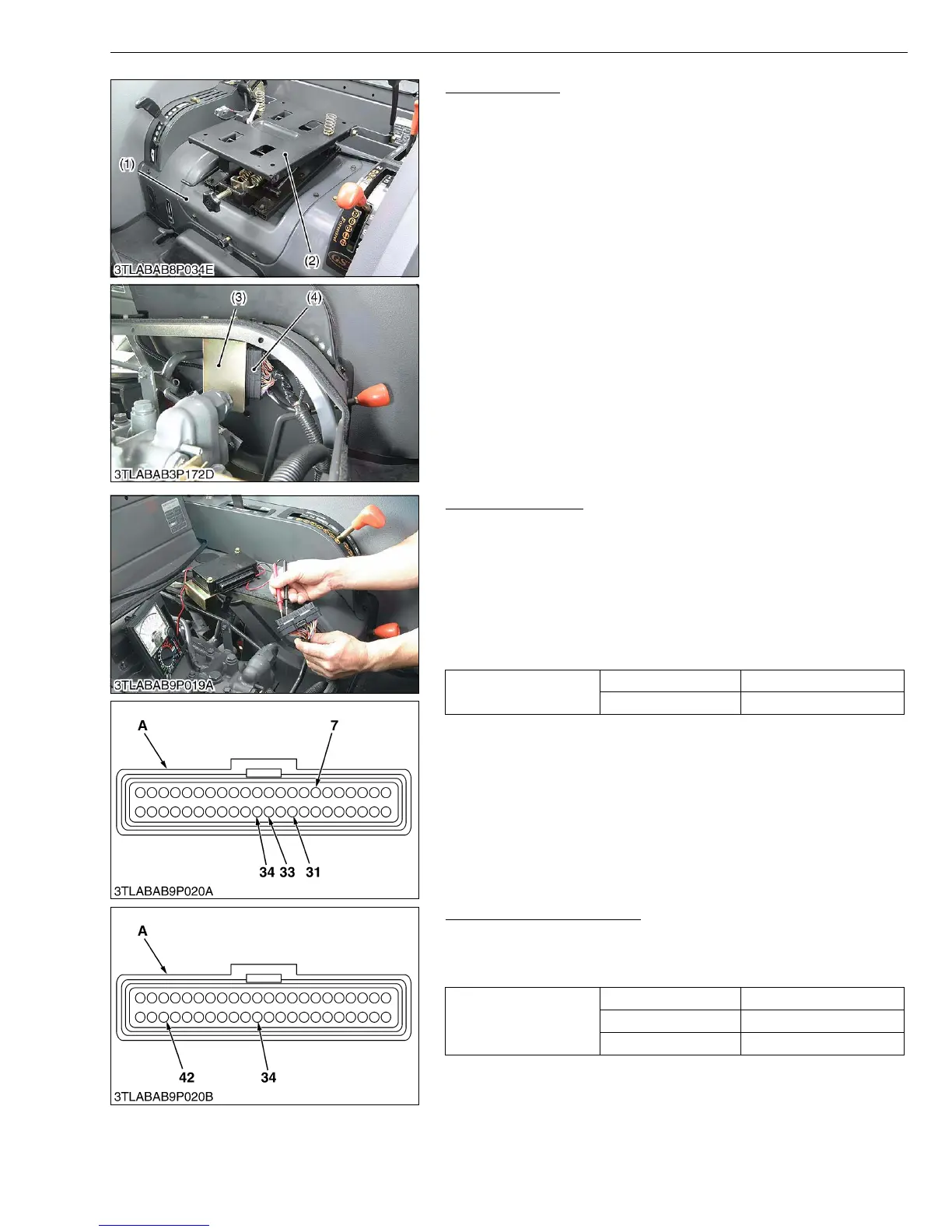
ECU Connector
1. Remove the seat.
2. Remove the seat bracket (1) with seat suspension (2) as a unit.
3. Disconnect the ECU connector (4).
W1039817
Connector Voltage
(Main Circuit)
1. Turn on the main switch. (Do not start engine.)
2. Measure the voltage between terminal 31 (+) and terminal 7 (–).
3. It is OK if the voltage equals to the battery voltage.
(Sensor Voltage)
1. Turn on the main switch. (Do not start engine.)
2. Measure the voltage between terminal 34 (+) and terminal 33 (–).
3. It is OK if the voltage is approx. 5 V.
W1039947
GST Lever Sensor Voltage
1. Turn on the main switch. (Do not start engine.)
2. Measure the voltage between terminal 42 (+) and terminal 34 (–).
3. It is OK if the voltage comes to show in the table below.
W1040168
(1) Seat Bracket
(2) Seat Suspension
(3) ECU (Electric Control Unit)
(4) ECU Connector
Voltage
Terminal 31 to 7 Approx. battery voltage
Terminal 34 to 33 Approx. 5 V
A : Connector of wire harness side
Voltage between
terminal 42 to 34
GST lever at Neutral Approx. 0.7 V
GST lever at 8th Approx. 3.07 V
GST lever at 12th Approx. 4.21 V
A : Connector of wire harness side



 To Next Page