9-S50
L3130 · L3430 · L3830 · L4630 · L5030, WSM
ELECTRICAL SYSTEM
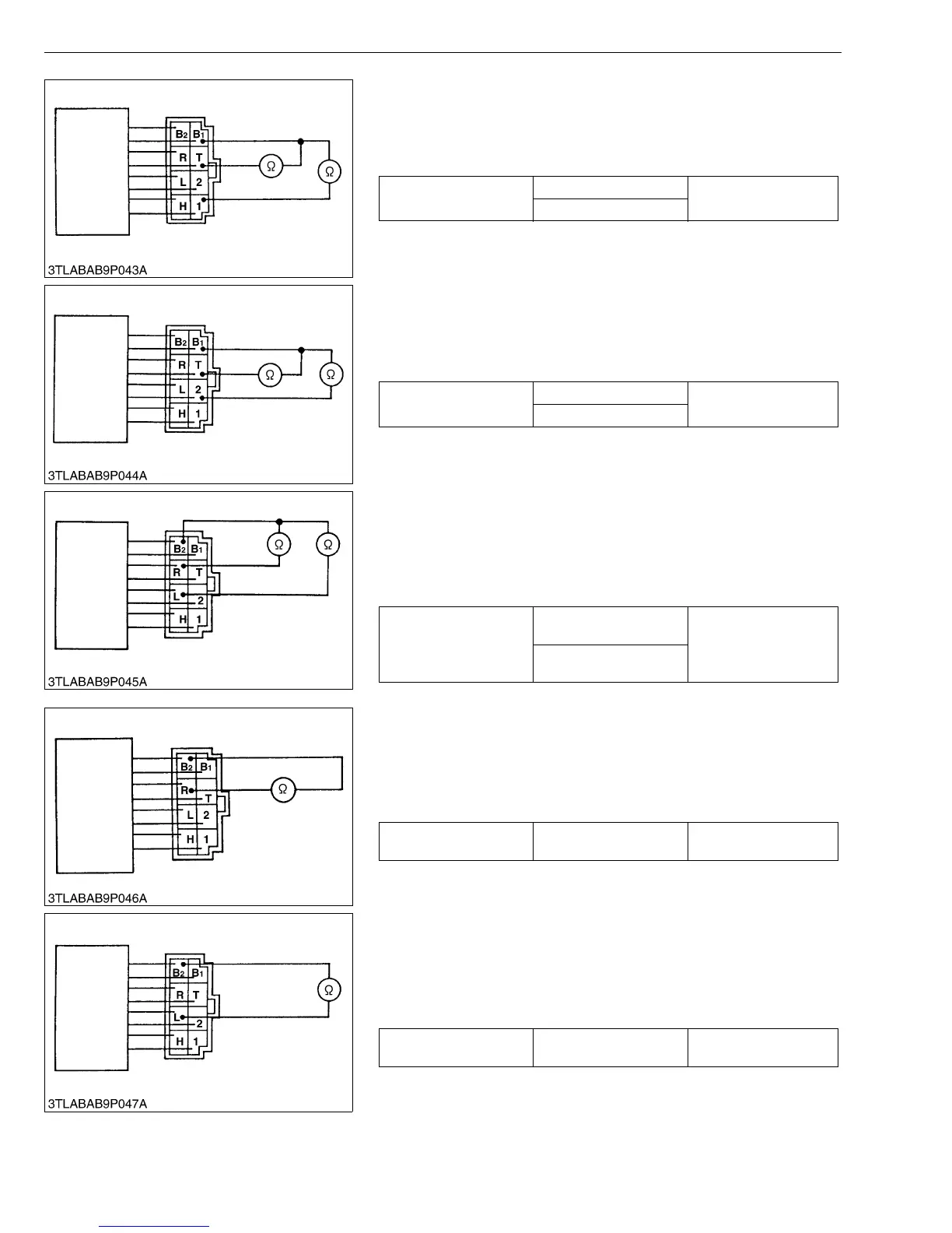
3) Light Switch Continuity when Setting Switch at HIGH-BEAM
Position
1. Measure the resistance between the terminal B
1 and the terminal
T, the terminal 1.
2. If 0 Ω is not indicated, the head light switch is faulty.
W1043473
4) Light Switch Continuity when Setting Switch at LOW-BEAM
Position
1. Measure the resistance between the terminal B
1 and the terminal
T, the terminal 2.
2. If 0 Ω is not indicated, the head light switch is faulty.
W1044119
5) Turn Signal Light Switch when Setting Switch Knob at OFF
Position
1. Set the turn signal light switch to the OFF position.
2. Measure the resistance between the terminal B
2 and the terminal
R, the terminal L.
3. If infinity is not indicated, the turn signal light switch is faulty.
W1044501
6) Turn Signal Light Switch when Setting Switch Knob at R
Position
1. Set the turn signal light switch to the R position.
2. Measure the resistance between the terminal B
2 and the terminal
R.
3. If 0 Ω is not indicated, the turn signal light switch is faulty.
W1044955
7) Turn Signal Light Switch when Setting Switch Knob at L
Position
1. Set the turn signal light switch to the L position.
2. Measure the resistance between the terminal B
2 and the terminal
L.
3. If 0 Ω is not indicated, the turn signal light switch is faulty.
W1045932
Resistance (Switch at
HIGH-BEAM position)
Terminal B
1 – Terminal T
0 Ω
Terminal B
1 – Terminal 1
Resistance (Switch at
LOW-BEAM position)
Terminal B
1 – Terminal T
0 Ω
Terminal B
1 – Terminal 2
Resistance (Switch at
OFF position)
Terminal B
2 –
Terminal R
Infinity
Terminal B
2 –
Terminal L
Resistance (Switch at R
position)
Terminal B2 –
Terminal R
0 Ω
Resistance (Switch at L
position)
Terminal B2 –
Terminal L
0 Ω