9-S51
L3130 · L3430 · L3830 · L4630 · L5030, WSM
ELECTRICAL SYSTEM
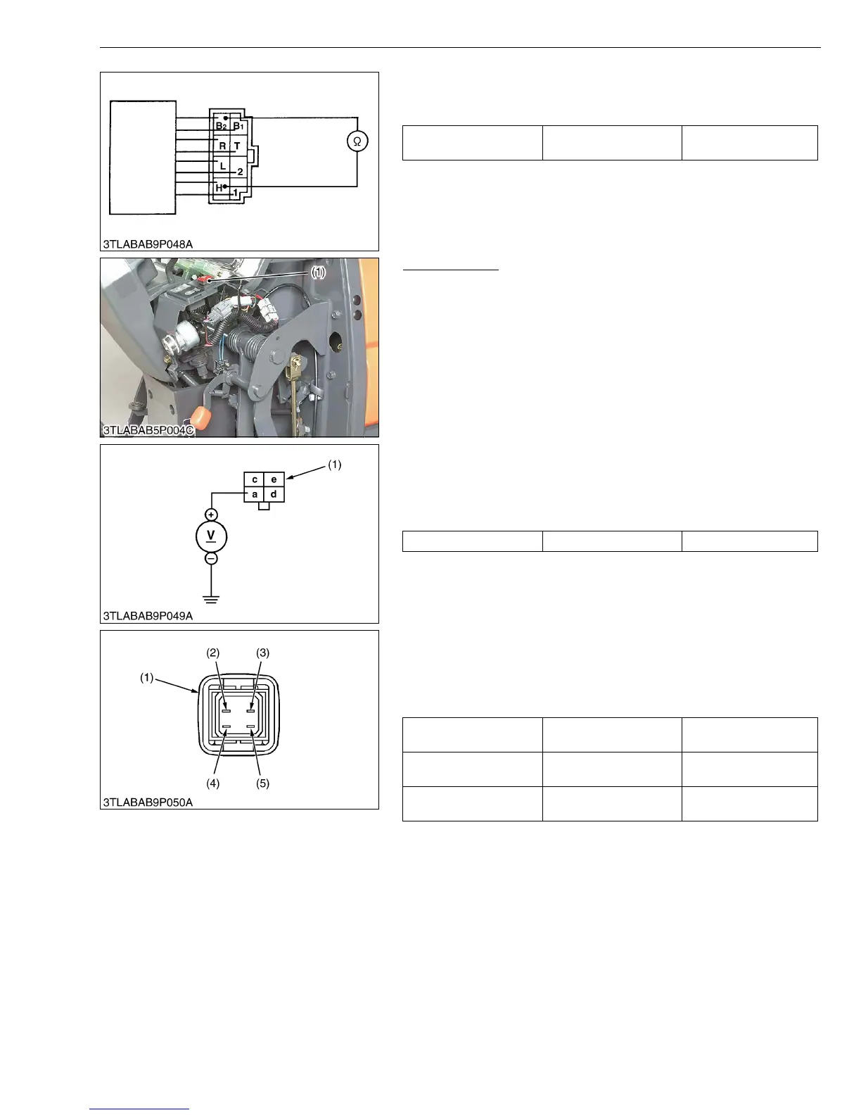
8) Horn Switch (If equipped)
1. Measure the resistance across the B
1 terminal to the H terminal.
2. If 0 ohm is not indicated, the horn switch is faulty.
W1074245
Hazard Switch
1. Remove the meter panel and disconnect the 4P connector from
hazard switch (1) after disconnect the battery negative code.
2. Remove the hazard switch (1).
3. Perform the following checking.
W1059839
1) Connector Voltage
1. Connect the battery negative code, then measure the voltage
across the terminal a and chassis.
2. If the voltage differ from the battery voltage, the wiring harness is
faulty.
W1060059
2) Hazard Switch Continuity
1. Measure the resistance with ohmmeter across the terminal a and
terminal c, and across the terminal d and terminal e.
2. If the measurement is not following below, the hazard switch or
the bulb are faulty.
W1060293
Resistance (Horn switch
is pushed)
B
1 terminal – H terminal 0 Ω
(1) Hazard Switch
Voltage Terminal a – Chassis Approx. battery voltage
(1) 4P Connector
Resistance
(Switch at OFF)
Terminal a – Terminal c Infinity
Resistance
(Switch at ON)
Terminal a – Terminal c 0 Ω
Resistance
(Bulb)
Terminal d – Terminal e Approx. 13 Ω
(1) Hazard Switch Connector
(2) Terminal a
(3) Terminal d
(4) Terminal c
(5) Terminal e