7 Series FPGAs GTP Transceivers User Guide www.xilinx.com 215
UG482 (v1.9) December 19, 2016
FPGA RX Interface
Table 4-47 defines the FPGA RX interface attributes.
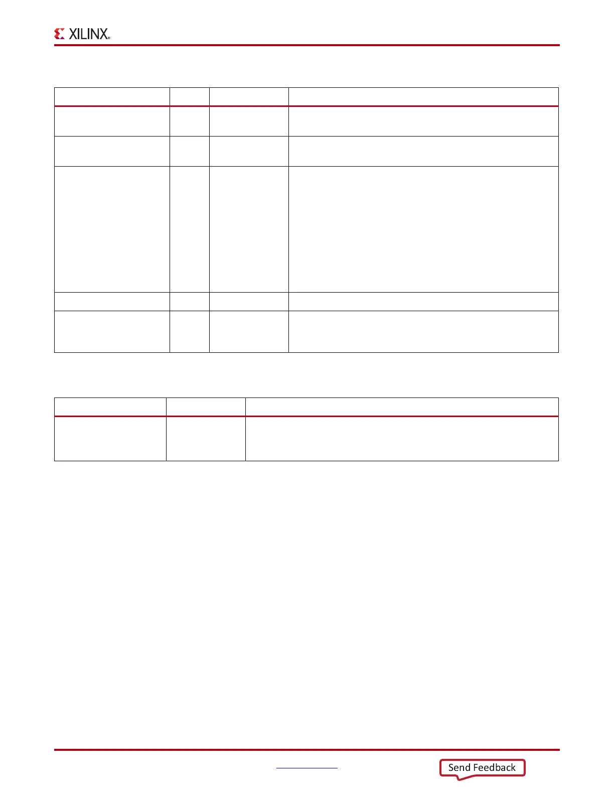
Table 4-46: FPGA RX Interface Ports
Port Dir Clock Domain Description
RXDISPERR[3:0] Out RXUSRCLK2 When 8B/10B decoding is disabled, RXDISPERR is used to extend
the data bus for 20-bit and 40-bit RX interfaces.
RXCHARISK[3:0] Out RXUSRCLK2 When 8B/10B decoding is disabled, RXCHARISK is used to extend
the data bus for 20-bit and 40-bit RX interfaces.
RXDATA[31:0] Out RXUSRCLK2 The bus for transmitting data. The width of this port depends on
RX_DATA_WIDTH:
RX_DATA_WIDTH = 16, 20:
RXDATA[15:0] = 16 bits wide
RX_DATA_WIDTH = 32, 40:
RXDATA[31:0] = 32 bits wide
When a 20-bit or 40-bit bus is required, the RXCHARISK and
RXDISPERR ports from the 8B/10B encoder are concatenated with
the RXDATA port. See Table 4-44, page 214.
RXUSRCLK In Clock This port is used to provide a clock for the internal RX PCS datapath.
RXUSRCLK2 In Clock This port is used to synchronize the FPGA logic with the RX
interface. This clock must be positive-edge aligned to RXUSRCLK
when RXUSRCLK is provided by the user.
Table 4-47: FPGA RX Interface Attributes
Attribute Type Description
RX_DATA_WIDTH Integer Sets the bit width of the RXDATA port. When 8B/10B encoding is enabled,
RX_DATA_WIDTH must be set to 20 or 40. Valid settings are 16, 20, 32, or 40.
See Interface Width Configuration, page 214 for more details.