94 www.xilinx.com 7 Series FPGAs GTP Transceivers User Guide
UG482 (v1.9) December 19, 2016
Chapter 3: Transmitter
Ports and Attributes
Table 3-13 defines the TX buffer ports.
Table 3-14 defines the TX buffer attributes.
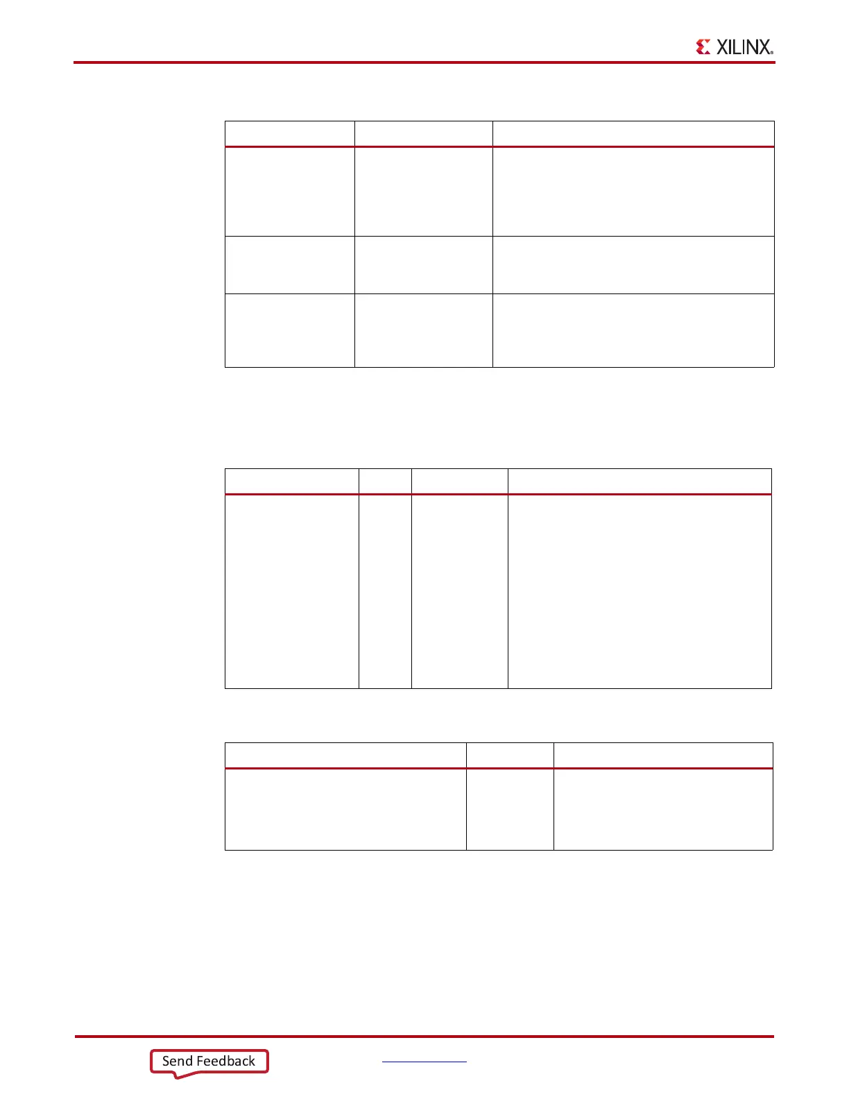
Table 3-12: TX Buffering versus Phase Alignment
TX Buffer TX Phase Alignment
Ease of Use The TX buffer is the
recommended default
to use when possible. It
is robust and easier to
operate.
Phase alignment is an advanced feature that
requires extra logic and additional constraints on
clock sources. TXOUTCLKSEL must select the
GTP transceiver reference clock as the source of
TXOUTCLK to drive TXUSRCLK.
Latency If low latency is critical,
the TX buffer must be
bypassed.
Phase alignment uses fewer register in the TX
datapath to achieve lower and deterministic latency.
TX Lane-to-Lane
Deskew
The TX phase alignment circuit can be used to
reduce the lane skew between separate GTP
transceivers. All GTP transceivers involved must
use the same line rate.
Table 3-13: TX Buffer Ports
Port Dir Clock Domain Description
TXBUFSTATUS[1:0] Out TXUSRCLK2 TX buffer status.
TXBUFSTATUS[1]: TX buffer overflow or
underflow status. When TXBUFSTATUS[1] is
set High, it remains High until the TX buffer is
reset.
1: TX FIFO has overflow or underflow.
0: No TX FIFO overflow or underflow error.
TXBUFSTATUS[0]: TX buffer fullness.
1: TX FIFO is at least half full.
0: TX FIFO is less than half full.
Table 3-14: TX Buffer Attributes
Attribute Type Description
TXBUF_EN String Use or bypass the TX buffer.
TRUE: Uses the TX buffer (default).
FALSE: Bypasses the TX buffer
(advanced feature).