62Y5A11
5-44
1
2
3
4
5
6
7
8
9
NOTE:
Be sure not to put the Plastigauge (PG-1)
over the oil hole in the crank pin of the crank-
shaft.
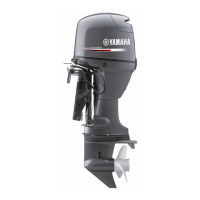
4. Install the connecting rod to the crank pin
3
.
NOTE:
• Align the alignment marks
b
on the con-
necting rod cap and connecting rod.
• Face the embossed “Y11” mark on the con-
necting rod toward the flywheel side of the
crankshaft.
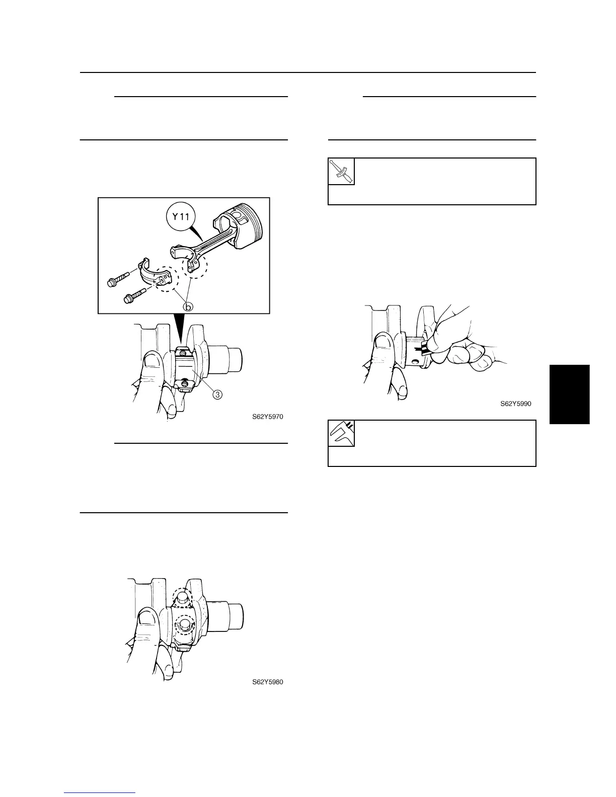
5. Tighten the connecting rod bolts to the
specified torques in two stages.
NOTE:
Do not turn the connecting rod until the crank
pin oil clearance measurement has been
completed.
6. Remove the connecting rod cap and
measure the width of the compressed
Plastigauge (PG-1) on each crank pin.
Replace the connecting rod bearing if out
of specification.
Connecting rod bolt:
1st: 6 N·m (0.6 kgf·m, 4.3 ft·lb)
2nd: 17 N·m (1.7 kgf·m, 12 ft·lb)
Crank pin oil clearance:
0.016–0.040 mm
(0.0006–0.0015 in)
Cylinder body