62Y5A11
5-46
1
2
3
4
5
6
7
8
9
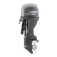
3. Select the suitable color
a
for the con-
necting rod bearing from the table.
4. When installing the connecting rod bear-
ing, insert the projection of the connect-
ing rod bearing into the slot on the
connecting rod.
CAUTION:
Remove any small metal particles and oil
from the contact surfaces of the connect-
ing rod and the connecting rod bearing.
5. Measure the crank pin oil clearance with
a piece of Plastigauge (PG-1).
6. If the oil clearance is below specification,
check the connecting rod bearing color
and clean the contact surface of the con-
necting rod and the connecting rod bear-
ing, and then check the crank pin oil
clearance again.
7. If the oil clearance is over specification,
install an over-sized connecting rod bear-
ing, and then check the crank pin oil
clearance again.
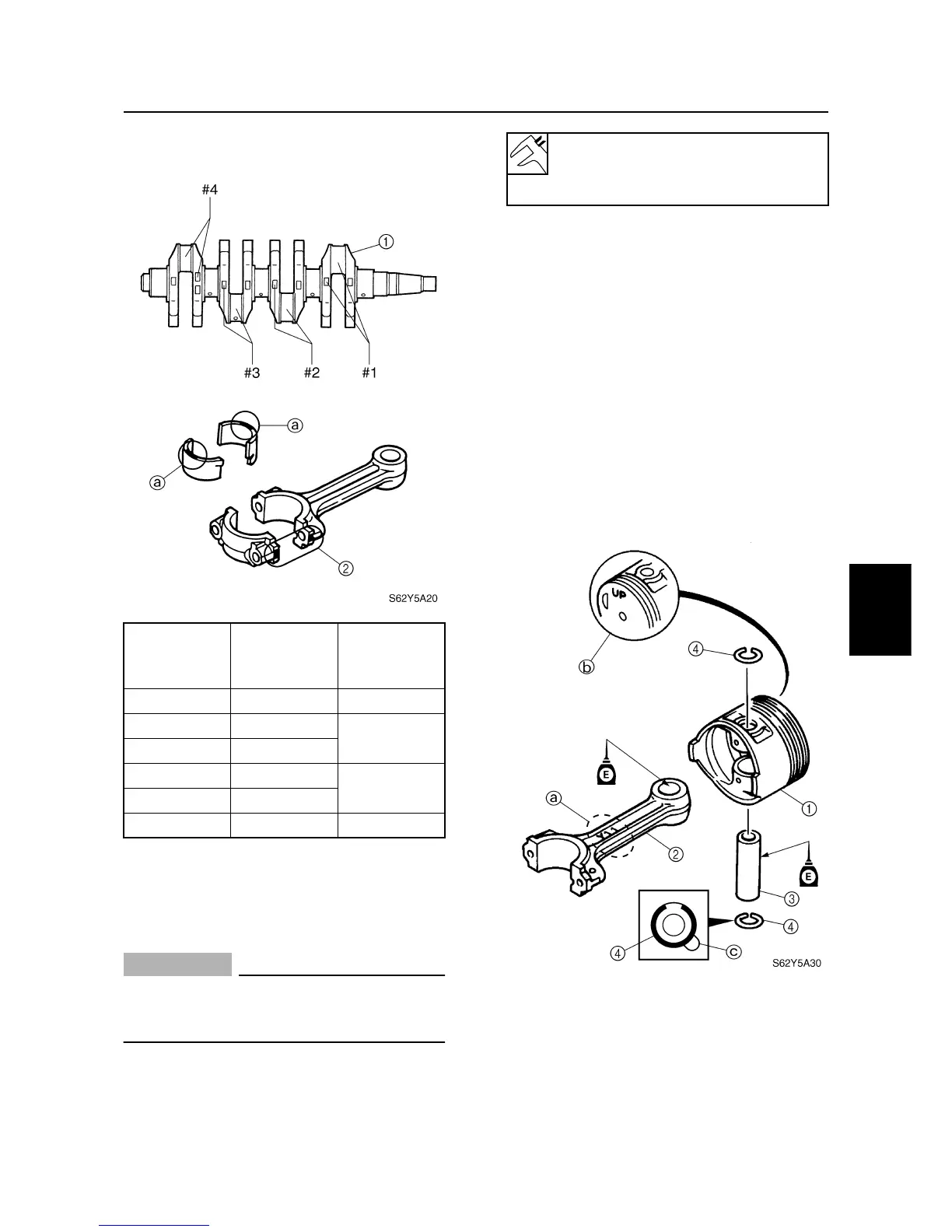
Assembling the cylinder body
1. Assemble the piston
1
, connecting rod
2
, piston pin
3
, and piston pin clips
4
.
Connecting
rod cap
mark/color
Crank pin
mark
Bearing
color
I
/Red A Yellow
I
/Red B
Red
II
/Blue A
II
/Blue B
Pink
III
/Yellow A
III
/Yellow B Green
Crank pin oil clearance:
0.016–0.040 mm
(0.0006–0.0015 in)
Cylinder body