SPEC
Specifications
2-15
62Y5A11
General torques
This chart specifies tightening torques for
standard fasteners with a standard ISO
thread pitch. Tightening torque specifications
for special components or assemblies are
provided in applicable sections of this man-
ual. To avoid warpage, tighten multi-fastener
assemblies in a crisscross fashion and pro-
gressive stages until the specified torque is
reached. Unless otherwise specified, torque
specifications require clean, dry threads.
Components should be at room temperature.
Bracket unit
Tiller handle assembly nut — 37 3.7 27
Throttle cable (short) locknut — 37 3.7 27
Upper mount nut — 24 2.4 17
Lower mount nut — 42 4.2 30
Trim sensor screw M6 2 0.2 1.4
Clamp bracket self-locking nut — 23 2.3 17
Power trim and tilt
Tilt cylinder end screw — 90 9.0 65
PTT motor bolt M5 4 0.4 2.9
Reservoir cap — 6.5 0.65 4.7
Trim cylinder end screw — 80 8.0 58
Tilt piston bolt M12 61 6.1 44
Relief valve bracket bolt M5 5.3 0.53 3.8
Gear pump assembly bolt M6 6.5 0.65 4.7
Gear pump bracket bolt M5 5.3 0.53 3.8
Electrical unit
Pulser coil screw — 40.42.9
Starter motor nut — 90.96.5
Part to be tightened Thread size
Tightening torques
N·mkgf·mft·lb
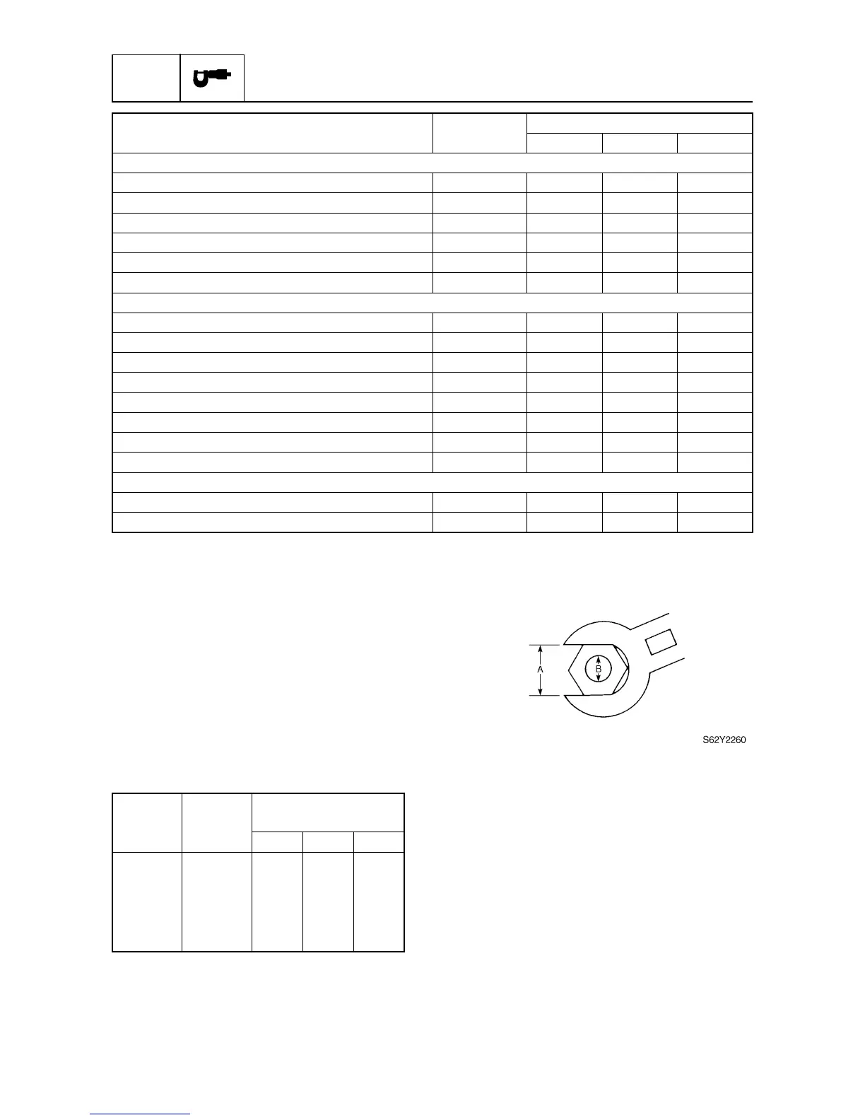
Nut (A) Bolt (B)
General torque
specifications
N·mkgf·mft·lb
8 mm M5 5 0.5 3.6
10 mm M6 8 0.8 5.8
12 mm M8 18 1.8 13
14 mm M10 36 3.6 25
17 mm M12 43 4.3 31