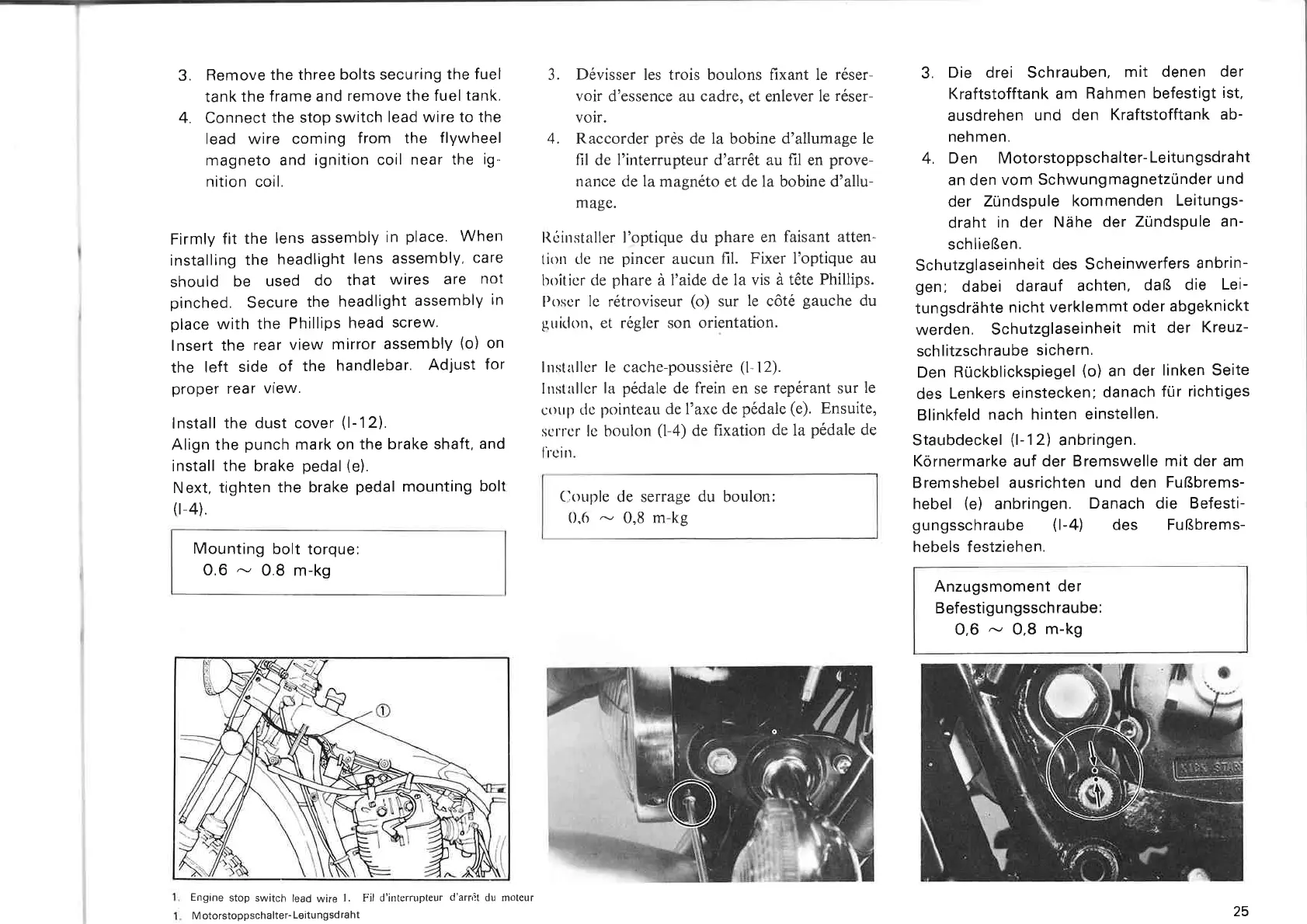
3. Rem
ove
the
three
bolts
se cu ring
the
fuel
tank
the
frame
and remove
the
fuel
tank
.
4.
Connect
the
stop
switch
lead
wire
ta
the
lead
w i
re
coming
from
the
flywheel
magneto
and
ignition
coil
near the ig-
nition
coil.
Firmly
fit
the
lens
assembly in
place.
When
installing
the
headlight
lens assembly. care
sh
ould
be used
do
that
wires
are n
ot
pinched. Secure the headli
ght
assembly
in
place
with
the
Ph
illips
head
screw
.
lnsert
the
rear
view
mirror
assembly
(o) on
the
left
side
of
the
handlebar.
Adjust
for
proper
rear vi
ew
.
lnstall
the
dust
caver
(1-12).
Align
the
punch
mark
on the brake
shaft
. and
install
the
brake pedal
(e)
.
N
ext
.
tighten
the
brake pedal
mounting
boit
(1-4).
Mounting
boit
torque
:
0.6
r-../
0.8
m-kg
1. Engine stop
switch
lead
wire
1.
Fil
d'interrupteur
d'arr.1t
du
moteur
3.
Dévisser
les
trois boulons fixant le
réser-
voir
d'essence
au
cadre,
et
enlever
le
réser-
voir.
4.
Raccorder près
de
la bobine d'allumage le
fil
de
l'interrupteur d'arrêt au
fil
en
prove-
nance
de
la magnéto et
de
la bobine
d'allu-
mage.
Réinstaller
l'optique du phare
en
faisant
atten-
tion
de
ne
pincer aucun fil. Fixer l'optique
au
boîtier
de
phare
à
l'aide
de
la vis
à
tête
Phillips.
Poser
le
rétroviseur (o) sur le côté gauche du
guidon,
et régler son
ori~ntation.
1
nstaller
le
cache-poussière
(1-12).
Installer
la pédale
de
frein
en
se
repérant sur le
coup
de
pointeau
de
l'axe
de
pédale
(e).
Ensuite,
serrer
le
boulon
(1-4)
de
fixation
de
la pédale
de
l'rein.
l
Couple
de
serrage du boulon:
0,6
r-../
0,8
rn-kg
3. Die drei
Schrauben
,
mit
denen
der
Kraftstofftank
am Rahmen
befestigt
ist.
ausdrehen und
den
Kraftstofftank
ab-
nehmen
.
4.
Den
Motorstoppschalter-Leitungsdraht
an den
vom
Schwungmagnetzünder
und
der
Zündspule
kommenden
Leitungs-
draht
in
der
Nahe
der
Zündspule an-
schlie~en.
Schutzglaseinhe
it des
Scheinwerfers
anbrin-
gen; dabei
darauf
achten,
da~
die
Le
i-
tungsdrahte
nicht
verklemmt
oder
abgeknickt
werden
.
Schutzglaseinheit
mit
der
Kreuz-
schlitzschraube sichern.
Den Rückblickspiegel (o) an der linken Seite
des Lenkers
einstecken;
danach
für
richtiges
Blinkfeld
nach
hinten
einstellen.
Staubdeckel
(1-12)
anbringen
.
K6rnermarke
auf
der
Bremswelle
mit
der
am
Bremshebel
ausrichten
und den
Fu~brems
hebel
(e)
anbringen.
Danach
die
Befesti-
gungsschraube
(1
-
4)
des
FufSbrems-
hebels festziehen.
Anzugsmoment
der
Befestigungsschraube:
0.6
"""
0.8
m-kg
1.
Motorstoppschalter-Leitungsdraht
25



 To Next Page