EasyManua.ls Logo

Yamaha XT500 - INSTALLATION GUIDE

Yamaha XT500
46 pages
Print Icon
To Next Page IconTo Next Page
To Previous Page IconTo Previous Page
Loading...
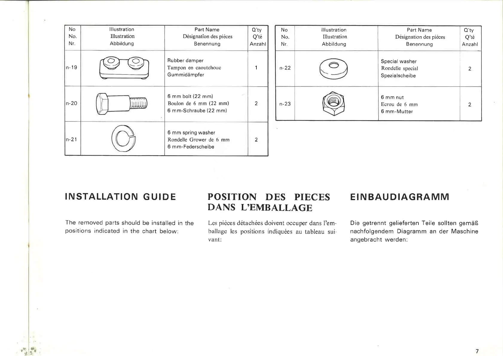
No
Illustration
Part
Name Q'
ty
No
Illustration
No
.
Illustration
Désignation
des
pièces
Q'
té
No
.
Illu
stration
Nr.
Abbildung
Benennung
Anzahl
Nr.
Abbildung
~~
Rubber
damper
n-19
Tampon
en
caoutchouc 1
Gummidampfer
®
n-22
~
6
mm
boit
(22 mm)
n-20
Boulon
de
6 mm (22 mm)
2
6
mm-Schraube
(22
mm)
~
n-23
@
6
mm
spring washer
n-21 Rondelle Grower
de
6
mm
2
6 mm-Federscheibe
INSTALLATION
GUIDE
POSITION
DES
PIECES
DANS
L'EMBALLAGE
The removed parts should
be
installed
in
the
positions
indicated in
the
chart
below
:
Les
pièces détachées doivent occuper dans l'em-
ballage les positions indiquées au tableau sui-
vant:
Part
Name
i
Q'
ty
Désignation
des
pièces
Q'
té
Benennung
1
Anzahl
Special
washer
Rondelle special
2
Spezialscheibe
6
mm
nut
Ecrou
de
6 mm
2
6
mm
-
Mutter
EINBAUDIAGRAMM
Die
getrennt
gelieferten Teile sollten
gemars
nachfolgendem
Diagramm
an
der Maschine
angebracht
werden
:
7