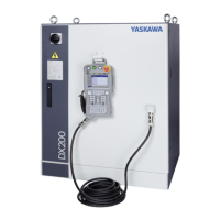
Description of Units and Circuit Boards
8 - 97
STICK DETECTION
This signal indicates an abnormal welding result or Power Source’s er-
ror. Alarm occurs and the manipulator stops if this signal is input during
welding.
GUN FULL OPEN DETECTION
This signal indicates that the stroke of the double stroke gun is full
open.
GUN SHORT OPEN DETECTION
This signal is connected with a single gun open verification limit switch
or a double stroke gun short open verification limit switch to verify the
gun open.
GUN PRESSURE DETECTION
This signal indicates that a gun is in pressing status.
TIP REPLACE COMPLETION
When this signal is input after tip replacement, the TIP REPLACE RE-
QUEST signal turns OFF, and the stored number of welding is cleared.
30057 TIP REPLACE REQUEST
This signal is output when the stored number of welding reaches the
number of welding set for the tip replacement.
30024 IN CUBE 3
This signal is turned ON when the current TCP lies within a pre-defined
area (cube 3). Use this signal to prevent faults due to other robots or
positioners.
30025 IN CUBE 4
This signal is turned ON when the current TCP lies within a pre-defined
area (cube 4). Use this signal to prevent faults due to other robots or
positioners.
30050
2
WELD ON/OFF
Outputs a signal input from the interlock panel, etc.considering the ro-
bot status.
30051
3
WELD ERROR RESET
This signal commands the reset error status of the power source. This
is operated with the programing pendant operation.
(30052 to
300564)
4
WELD CONDITION (Level-Signal)
1(1), 2(2), 4(3), 8(4), 16(5), 32(6), 64(7), 128(8)
Sets the welding conditions for the power source.
The output format can be set as binary or discrete (bit number.) It can
handle up to 255 conditions. Most-significant bit is the parity bit (when
specified).
WELDING COMMAND
This signal outputs execution command signal to the power source.
This signal is not necessary for a power source which is executed using
the WELDING CONDITION signal.
Logical num-
ber
Input name / Function

 Loading...


