Parameter Details
2
2.8 H: Terminal Function Selection
YASKAWA TOEPYAIGA5002A GA500 Programming 307
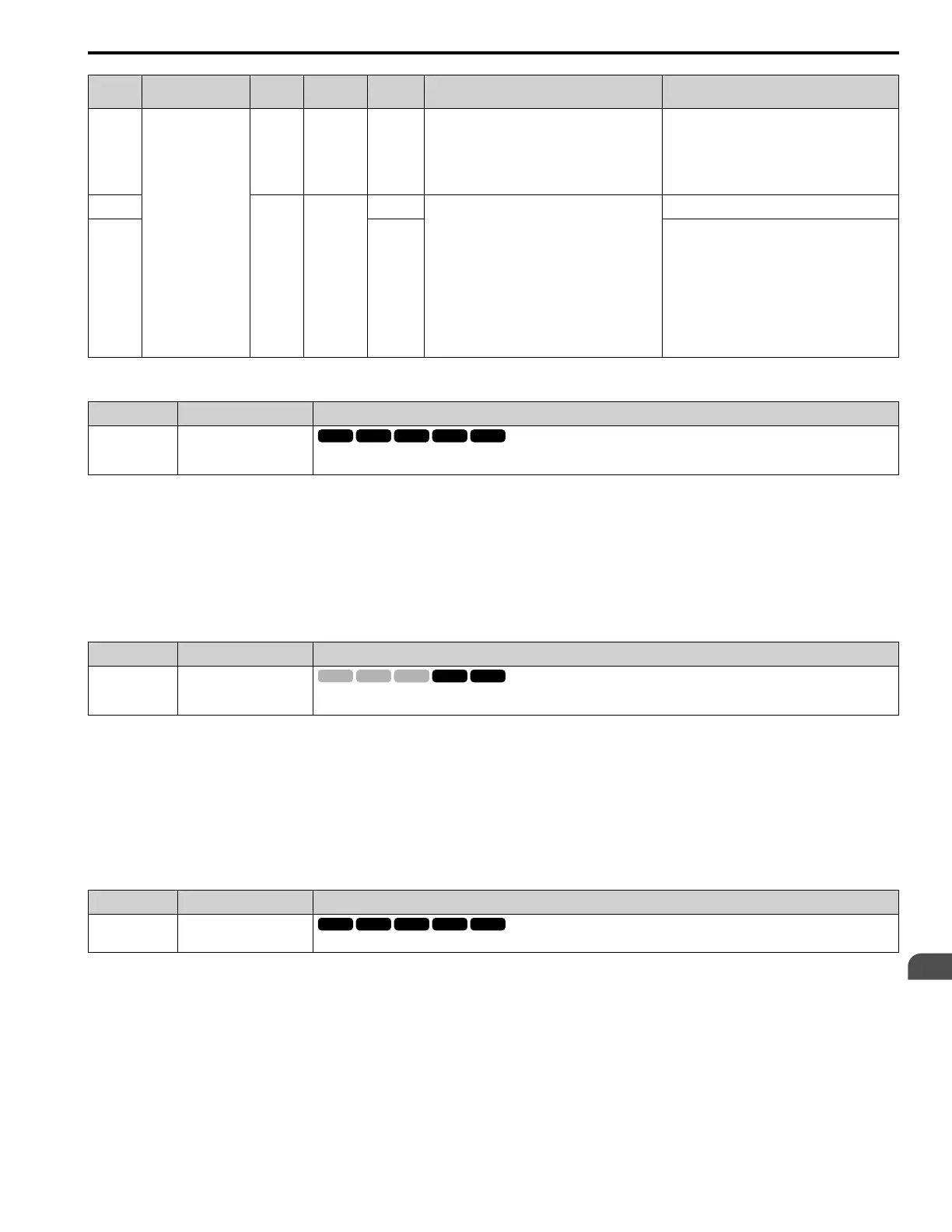
Function
Frequency
Reference Source
d4-03 d4-05 d4-01 Operation
Storing the Frequency Reference or
Frequency Bias
8
Others
(Analog input,
transmission)
0 1 -
• When the Up 2 Command is active, the drive
accelerates the motor (increases the bias value).
• When the Down 2 Command is active, the drive
decelerates the motor (decreases the bias value)
• For all other statuses, the drive will follow the
frequency reference.
Not stored.
9
> 0 -
0
• When the Up 2 Command is active, the drive
accelerates the motor to “Frequency Reference +
d4-03” (the bias value will increase to the value
set in d4-03)
• When the Down 2 Command is active, the drive
decelerates the motor to “Frequency Reference -
d4-03” (the bias value will decrease to the value
set in d4-03).
• During acceleration or deceleration, when the
frequency reference increases or decreases more
than d4-07, the drive holds the bias value until
the output frequency and the actual frequency
reference agree (speed agreement).
Not stored.
10 1
When the bias value is constant for 5 seconds after
the frequency reference hold starts, the drive will
store the bias value in d4-06. You cannot rewrite the
frequency reference is not possible. The drive will
store only the bias value.
■ 76: Down 2 Command
Setting Value Function Description
76 Down 2 Command
Sets the function to decrease the frequency reference bias value to decelerate the motor when the terminal is activated. Set this
function and H1-xx = 75 [Up 2 Command] at the same time.
When you activate the terminal set for Up2 Command, the bias will increase. When you activate the terminal set for
Down 2 Command, the bias will decrease. When you activate or deactivate the two commands, the drive will hold the
frequency reference.
Note:
• When you use this function, set the optimal bias limit values with d4-08 and d4-09 [Up/Down 2 Bias Upper Limit/Lower Limit].
• Refer to d4: Frequency Ref Up/Down & Hold on page 234 for more information.
■ 77: ASR Gain (C5-03) Select
Setting Value Function Description
77 ASR Gain (C5-03) Select
Sets the function to switch the ASR proportional gain set in C5-01 [ASR Proportional Gain 1] and C5-03 [ASR Proportional Gain
1/2].
ON : C5-03
Switches the proportional gain to C5-03 [ASR Proportional Gain 2].
OFF : C5-01
Switches the proportional gain to C5-01 [ASR Proportional Gain 1].
Note:
Refer to “C5: Automatic Speed Regulator (ASR)” for more information.
■ 7A: KEB Ride-Thru 2 Activate (N.C.)
Setting Value Function Description
7A KEB Ride-Thru 2 Activate
(N.C.)
Sets operation of the KEB2 function through the KEB Ride-Thru 2 (N.C.).
ON : Normal operation
OFF : Deceleration during momentary power loss
When KEB Ride-Thru 2 is input, the drive will use Single Drive KEB Ride-Thru 2 for KEB operation. The L2-29
[KEB Method Selection] setting will not have an effect.
Note:
• If you set KEB Ride-Thru 1 [H1-xx = 65, 66] and KEB Ride-Thru 2 [H1-xx = 7A, 7B] at the same time, the drive will detect oPE03 [Multi-
Function Input Setting Err].
• Refer to KEB Ride-Thru Function on page 364 for more information.

 Loading...


