5.4 Control Circuit Wiring
504 YASKAWA TOEPYAIGA5002A GA500 Programming
5.4 Control Circuit Wiring
This section gives information about how to correctly wire the control circuit.
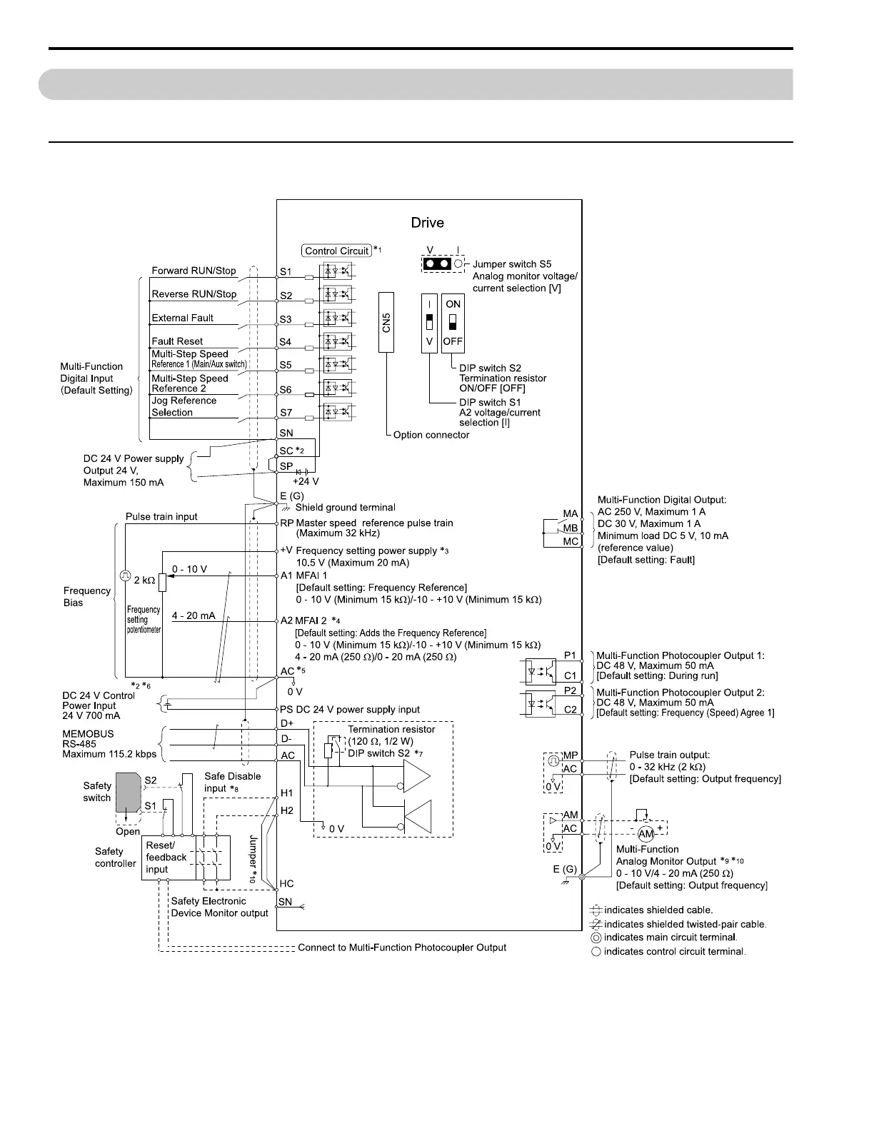
◆ Control Circuit Connection Diagram
Wire the drive control circuit as shown in Figure 5.3.
Figure 5.3 Control Circuit Connection Diagram
*1 Connect a 24 V power supply to terminals PS-AC to operate the control circuit while the main circuit power supply is OFF.

 Loading...


