5.3 Main Circuit Wiring
502 YASKAWA TOEPYAIGA5002A GA500 Programming
5.3 Main Circuit Wiring
This section gives information about the functions, specifications, and procedures necessary to safely and correctly
wire the main circuit in the drive.
NOTICE: Damage to Equipment. Do not energize and de-energize the drive more frequently than one time each 30 minutes. If you
frequently energize and de-energize the drive, it can cause drive failure.
Note:
Soldered wire connections can become loose over time and cause unsatisfactory drive performance.
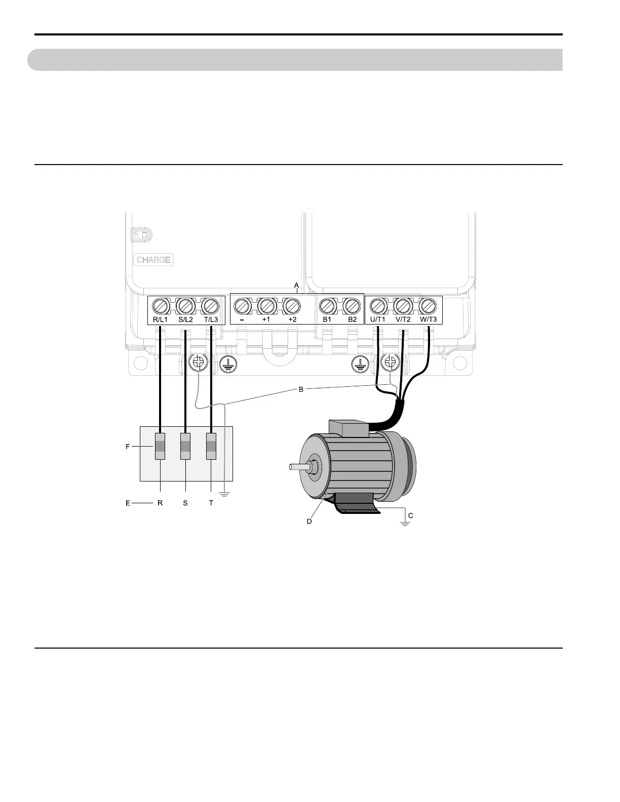
◆ Motor and Main Circuit Connections
WARNING! Electrical Shock Hazard. Do not connect terminals R/L1, S/L2, T/L3, L/L1, N/L2, U/T1, V/T2, W/T3, -, +1, +2, B1, or B2
to the ground terminal. If you connect these terminals to earth ground, it can cause damage to the drive or serious injury or death.
Note:
The locations of terminals are different for different drive models.
A - DC bus terminal
B - Connect to the drive ground terminal.
C - Ground the motor case.
D - Three-Phase Motor
E - Use terminals R/L1, S/L2, and T/L3 for three-
phase power supply input. Use terminals L/L1 and
N/L2 for single-phase power supply input.
F - Input Protection (Fuses or Circuit Breakers)
Figure 5.2 Wiring the Main Circuit and Motor
◆ Main Circuit Terminal Functions
Refer to Table 5.1 for the functions of drive main circuit terminals.

 Loading...


