Parameter Details
2
2.8 H: Terminal Function Selection
YASKAWA TOEPYAIGA5002A GA500 Programming 319
Note:
Parameter A1-02 [Control Method Selection] selects which parameter is the reference.
A1-02 Setting Control Method Selection Parameter Used as the Reference
0 V/f E1-09
2 OLV b2-01
5 OLV/PM E1-09
6 AOLV/PM E1-09
8 EZOLV E1-09
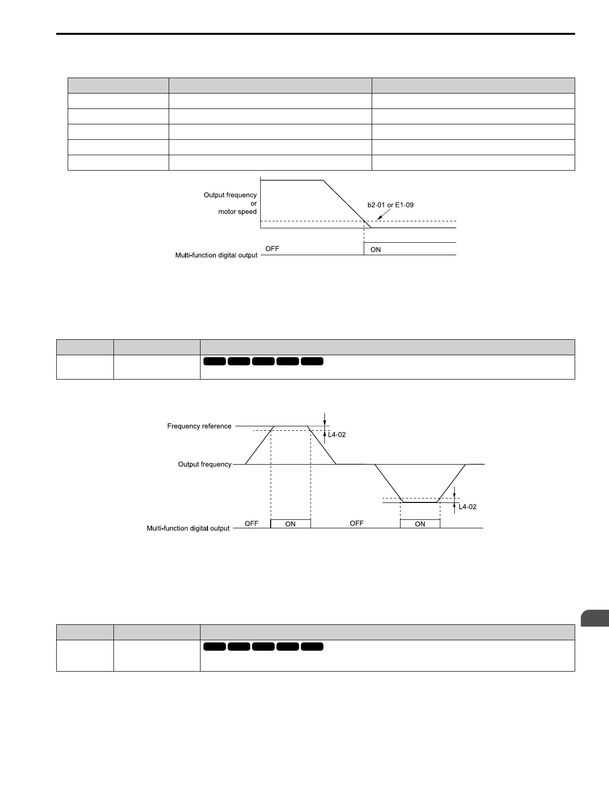
Figure 2.74 Zero Speed Time Chart
ON : Output frequency < value of E1-09 or b2-01.
OFF : Output frequency ≥ value of E1-09 or b2-01.
■ 2: Speed Agree 1
Setting Value Function Description
2 Speed Agree 1
The terminal activates when the output frequency is in the range of the frequency reference ± L4-02 [Speed Agree Detection Width].
Note:
The detection function operates in the two motor rotation directions.
Figure 2.75 Speed Agree 1 Time Chart
ON : The output frequency is in the range of “frequency reference ± L4-02”.
OFF : The output frequency does not align with the frequency reference although the drive is
running.
■ 3: User-Set Speed Agree 1
Setting Value Function Description
3 User-Set Speed Agree 1
The terminal activates when the output frequency is in the range of L4-01 [Speed Agree Detection Level] ± L4-02 [Speed Agree
Detection Width] and in the range of the frequency reference ± L4-02.
Note:
The detection function operates in the two motor rotation directions. The drive uses the L4-01 value as the forward/reverse detection level.
ON : The output frequency is in the range of “L4-01 ± L4-02” and the range of frequency reference ±
L4-02.

 Loading...


