Parameter List
1
1.10 H: Terminal Functions
YASKAWA TOEPYAIGA5002A GA500 Programming 61
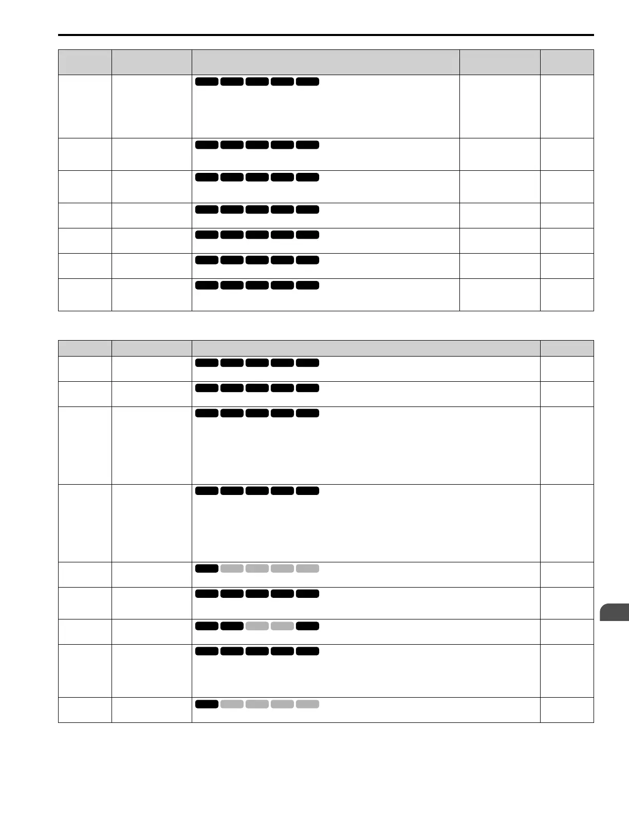
No.
(Hex.)
Name Description
Default
(Range)
Ref.
H3-14
(041C)
Analog Input Terminal
Enable Sel
Sets the enabled terminal or terminals when H1-xx = C [MFDI Function Select = Analog
Terminal Enable Selection] is ON.
1 : Terminal A1 only
2 : Terminal A2 only
7 : Terminals A1 and A2
7
(1, 2, 7)
336
H3-16
(02F0)
Terminal A1 Offset
Sets the offset level for analog signals input to terminal A1. Usually it is not necessary to
change this setting.
0
(-500 - +500)
336
H3-17
(02F1)
Terminal A2 Offset
Sets the offset level for analog signals input to terminal A2. Usually it is not necessary to
change this setting.
0
(-500 - +500)
336
H3-40
(0B5C)
Mbus Reg 15C1h Input
Function
Sets the MEMOBUS AI1 function.
F
(4 - 2F)
336
H3-41
(0B5F)
Mbus Reg 15C2h Input
Function
Sets the MEMOBUS AI2 function.
F
(4 - 2F)
337
H3-42
(0B62)
Mbus Reg 15C3h Input
Function
Sets the MEMOBUS AI3 function.
F
(4 - 2F)
337
H3-43
(117F)
Mbus Reg Inputs
FilterTime Const
Sets the time constant to apply a primary delay filter to the MEMOBUS analog input
register values.
0.00 s
(0.00 - 2.00 s)
337
■ H3-xx: MFAI Setting Values
Setting Value Function Description Ref.
0 Frequency Reference
The input value from the MFAI terminal set with this function becomes the master frequency reference.
337
1 Frequency Gain
The drive multiplies the analog frequency reference with the input value from the MFAI set with this function.
337
2 Auxiliary Frequency
Reference 1
Sets Reference 2 through multi-step speed reference to enable the command reference (Auxiliary Frequency Reference
1) from the analog input terminal set here. This value is a percentage where the Maximum Output Frequency setting is
a setting value of 100%.
Note:
Parameter A1-02 [Control Method Selection] selects which parameter is the maximum output frequency.
• A1-02 ≠ 8 [EZOLV]: E1-04 [Maximum Output Frequency]
• A1-02 = 8: E9-02 [Maximum Speed]
338
3 Auxiliary Frequency
Reference 2
Sets Reference 3 through multi-step speed reference to enable the command reference (Auxiliary Frequency Reference
2) from the analog input terminal set here. This value is a percentage where the Maximum Output Frequency setting is
a setting value of 100%.
Note:
Parameter A1-02 [Control Method Selection] selects which parameter is the maximum output frequency.
• A1-02 ≠ 8 [EZOLV]: E1-04 [Maximum Output Frequency]
• A1-02 = 8: E9-02 [Maximum Speed]
338
4 Output Voltage Bias
Set this parameter to input a bias signal to amplify the output voltage.
338
5 Accel/Decel Time Gain
Enters a signal to adjust the gain used for C1-01 to C1-08 [Acceleration/Deceleration Times 1 to 4] and C1-09 [Fast
Stop Time] when the full scale analog signal (10 V or 20 mA) is 100%.
338
6 DC Injection Braking
Current
Enters a signal to adjust the current level used for DC Injection Braking when the drive rated output current is 100%.
339
7 Torque Detection Level
Enters a signal to adjust the overtorque/undertorque detection level.
Note:
Use this function with L6-01 [Torque Detection Selection 1]. This parameter functions as an alternative to L6-02
[Torque Detection Level 1].
339
8 Stall Prevent Level during
Run
Enters a signal to adjust the stall prevention level during run if the drive rated current is 100%.
339

 Loading...


