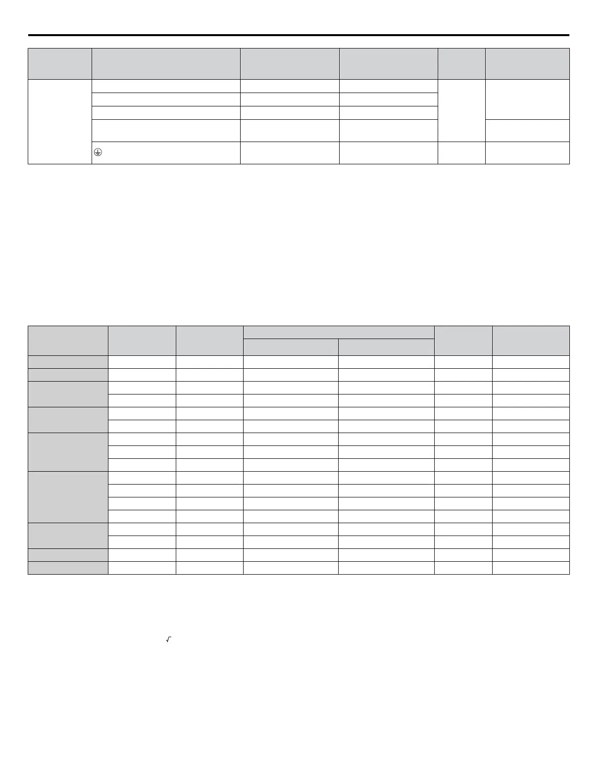
Drive
Model
Terminal
Recomm.
Gauge
AWG, kcmil
Wire Range
AWG, kcmil
Screw
Size
Tightening
Torque
N•m (lb.in.)
4A0038
R/L1, S/L2, T/L3 6 10 to 6
M5
3.6 to 4.0
(31.8 to 35.4)
U/T1, V/T2, W/T3 8 10 to 6
, 1, 2
– 10 to 6
B1, B2 – 10 to 8
2.7 to 3.0
(23.9 to 26.6)
6 10 to 6 M6
5.4 to 6.0
(47.8 to 53.1)
<1> When an EMC filter is installed, additional measures must be taken to comply with IEC/EN 61800-5-1. Refer to EMC Filter Installation on page
424 for details.
Note: Use crimp insulated terminals or insulated tubing for wiring these connections. Wires should have a continuous maximum allowable
temperature of 75 °C 600 V UL approved vinyl sheathed insulation. Ambient temperature should not exceed 30 °C.
Closed-Loop Crimp Terminal Recommendations
Yaskawa recommends crimp terminals made by JST and Tokyo DIP for the insulation cap.
Table D.9 matches the wire gauges and terminal screw sizes with Yaskawa-recommended crimp terminals, tools, and insulation
caps. Refer to the appropriate Wire Gauge and Torque Specifications table for the wire gauge and screw size for your drive
model. Place orders with a Yaskawa representative or the Yaskawa sales department.
The closed-loop crimp terminal sizes and values listed in Table D.9 are Yaskawa recommendations. Refer to local codes for
proper selections.
Table D.9 Closed-Loop Crimp Terminal Sizes
Wire Gauge
Terminal
Screws
Crimp Terminal
Model Number
Tool Insulation
Cap
Model No.
Code
<1>
Machine No. Die Jaw
18 AWG M3.5 R1.25-3.5 YA-4 AD-900 TP-003 100-066-217
16 AWG M3.5 R1.25-3.5 YA-4 AD-900 TP-003 100-066-217
14 AWG
M3.5 R2-3.5 YA-4 AD-900 TP-003 100-066-218
M4 R2-4 YA-4 AD-900 TP-003 100-054-028
12 / 10 AWG
M4 R5.5-4 YA-4 AD-900 TP-005 100-054-029
M5 R5.5-5 YA-4 AD-900 TP-005 100-054-030
8 AWG
M4 8-4 YA-4 AD-901 TP-008 100-054-031
M5 R8-5 YA-4 AD-901 TP-008 100-054-032
M8 R8-8 YA-4 AD-901 TP-008 100-061-111
6 AWG
M4 14-4 YA-4 AD-902 TP-014 100-66-220
M5 R14-5 YA-4 AD-902 TP-014 100-054-034
M6 R14-6 YA-5 AD-952 TP-014 100-051-261
M8 R14-8 YA-5 AD-952 TP-014 100-054-035
4 AWG
M6 R22-6 YA-5 AD-953 TP-022 100-051-262
M8 R22-8 YA-5 AD-953 TP-022 100-051-263
3 AWG M8 R38-8 YA-5 AD-954 TP-038 100-051-264
2 AWG M8 R38-8 YA-5 AD-954 TP-038 100-051-264
<1> Codes refer to a set of three crimp terminals and three insulation caps. Prepare input and output wiring using two sets for each connection.
Example: Models with 14 AWG for both input and output require one set for input terminals and one set for output terminals, so the user should
order two sets of [100-066-218].
Note: Consider the amount of voltage drop when selecting wire gauges. Increase the wire gauge when the voltage drop is greater than 2% of motor
rated voltage. Ensure the wire gauge is suitable for the terminal block. Use the following formula to calculate the amount of voltage drop:
Line drop voltage (V) =
3 × wire resistance (Ω/km) × wire length (m) × current (A) × 10
-3
n
Factory Recommended Branch Circuit Protection
Yaskawa recommends installing one of the following types of branch circuit protection to maintain compliance with UL508C.
Semiconductor protective type fuses are preferred.
Branch circuit protection shall be provided by any of the following according to
Table D.10.
• Non-time Delay Class J, T, or CC fuses.
• Time Delay Class J, T, CC, or RK5 fuses.
D.3 UL and CSA Standards
430
YASKAWA TOEP YAIQPM 03B YASKAWA AC Drive - iQpump Micro User Manual

 Loading...


