14.3 DO–01 (Digital Output) Module
14.3.8 Standard Cable Wiring Table
65
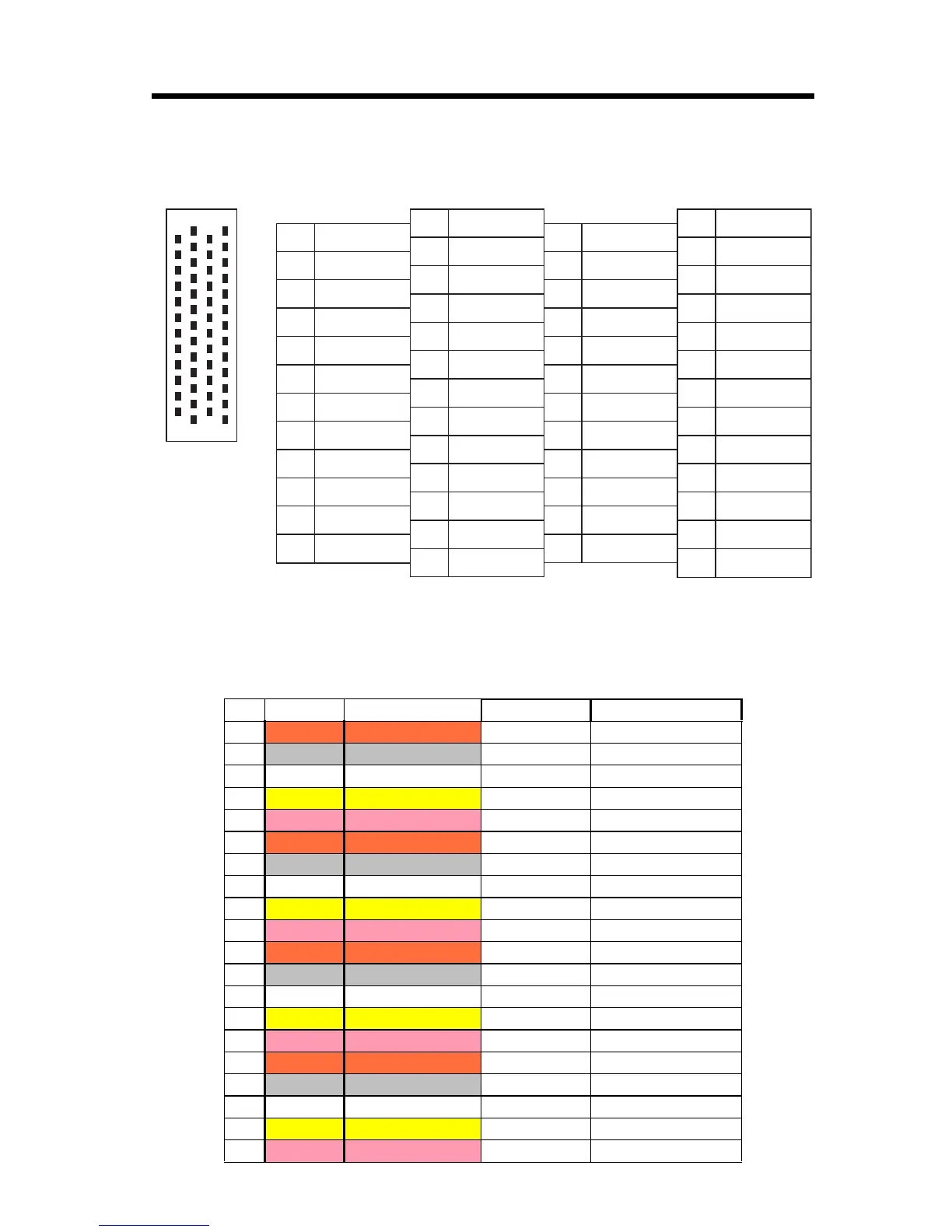
CN2 Connector Pin Arrangement
14.3.8 Standard Cable Wiring Table
The wiring table for the standard cable JEPMC-W6060- is shown
below.
Pin Wire Color Marking Signal Name Function
1
Orange
+24V_1/5 24V power supply 1/5
2
Gray
DO_00/32 Digital output 0/32
3White
DO_02/34 Digital output 2/34
4
Yellow
DO_04/36 Digital output 4/36
5
Pink
DO_06/38 Digital output 6/38
6
Orange
0V_1/5 Common ground 1/5
7
Gray
+24V_2/6 24V power supply 2/6
8White
DO_08/40 Digital output 8/40
9
Yellow
DO_10/42 Digital output 10/42
10
Pink
DO_12/44 Digital output 12/44
11
Orange
DO_14/46 Digital output 14/46
12
Gray
0V_2/6 Common ground 2/6
13 White
+24V_3/7 24V power supply 3/7
14
Yellow
DO_16/48 Digital output 16/48
15
Pink
DO_18/50 Digital output 18/50
16
Orange
DO_20/52 Digital output 20/52
17
Gray
DO_22/54 Digital output 22/54
18 White
0V_3/7 Common ground 3/7
19
Yellow
+24V_4/8 24V power supply 4/8
20
Pink
DO_24/58 Digital output 24/58
1
3
5
7
9
11
13
15
17
19
21
23
25
+24V_5
DO_34
DO_38
+24V_6
DO_42
DO_46
+24V_7
DO_50
DO_54
+24V_8
DO_58
DO_62
N.C.
26
28
30
32
34
36
38
40
42
44
46
48
50
OV_5
DO_35
DO_39
OV_6
DO_43
DO_47
OV_7
DO_51
DO_55
OV_8
DO_59
DO_63
N.C.
27
29
31
33
35
37
39
41
43
45
47
49
DO_33
DO_37
OV_5
DO_41
DO_45
OV_6
DO_49
DO_53
OV_7
DO_57
DO_61
OV_8
50
49
25
24
26
27
1
2
Pin Arrangement Viewed from Wiring Side
2
4
6
8
10
12
14
16
18
20
22
24
DO_32
DO_36
OV_5
DO_40
DO_44
OV_6
DO_48
DO_52
OV_7
DO_56
DO_60
OV_8