14.3 DO–01 (Digital Output) Module
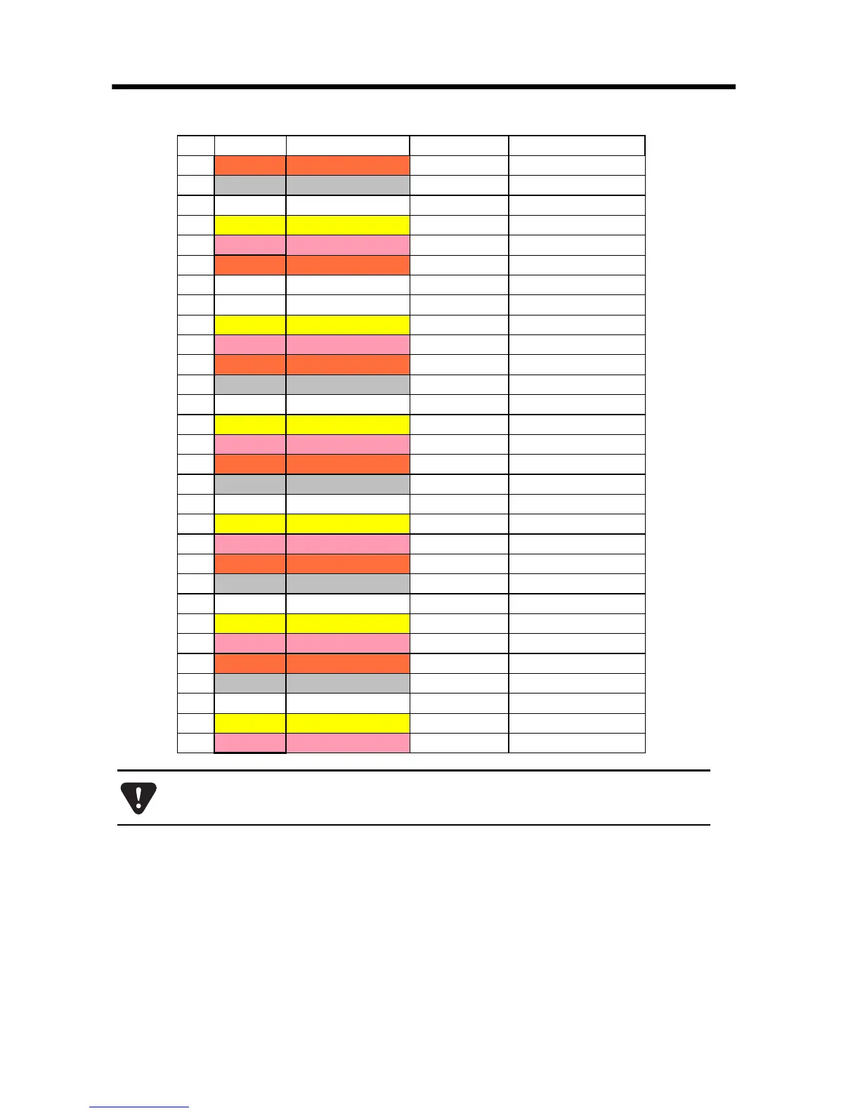
14.3.8 Standard Cable Wiring Table
66
21 Orange Continuous
DO_26/68 Digital output 26/60
22
Gray Continuous
DO_28/60 Digital output 28/62
23 White Continuous
DO_30/62 Digital output 30/64
24
Yellow Continuous
0V_4/8 Common ground 4/8
25
Pink Continuous
N.C
26
Orange —
0V_1/5 Common ground 1/5
27 Gray —
DO_01/33 Digital output 1/33
28 White —
DO_03/35 Digital output 3/35
29
Yellow —
DO_05/37 Digital output 5/37
30
Pink —
DO_07/39 Digital output 7/39
31
Orange — —
0V_1/5 Common ground 1/5
32
Gray — —
0V_2/6 Common ground 2/6
33 White — —
DO_09/41 Digital output 9/41
34
Yellow — —
DO_11/43 Digital output 11/43
35
Pink — —
DO_13/45 Digital output 13/45
36
Orange — — —
DO_15/47 Digital output 15/47
37
Gray — — —
0V_2/6 Common ground 2/6
38 White — — —
0V_3/7 Common ground 3/7
39
Yellow — — —
DO_17/49 Digital output 17/49
40
Pink — — —
DO_19/51 Digital output 19/51
41
Orange — — — Continuous
DO_21/53 Digital output 21/53
42
Gray — — — Continuous
DO_23/55 Digital output 23/55
43 White — — — Continuous
0V_3/7 Common ground 3/7
44
Yellow — — — Continuous
0V_4/8 Common ground 4/8
45
Pink — — — Continuous
DO_25/57 Digital output 25/57
46
Orange — — — —
DO_27/59 Digital output 27/59
47
Gray ————————
DO_29/61 Digital output 29/61
48 White ————————
DO_31/63 Digital output 31/63
49
Yellow ————————
0V_4/8 Common ground 4/8
50
Pink ————————
N.C
Columns “Signal Name” and “Function” display the values for connectors CN1
and CN2 in the format “CN1/CN2” respectively.
Pin Wire Color Marking Signal Name Function