14.5 LIO-04/05 Modules
14.5.4 Switch Settings
78
14.5.4 Switch Settings
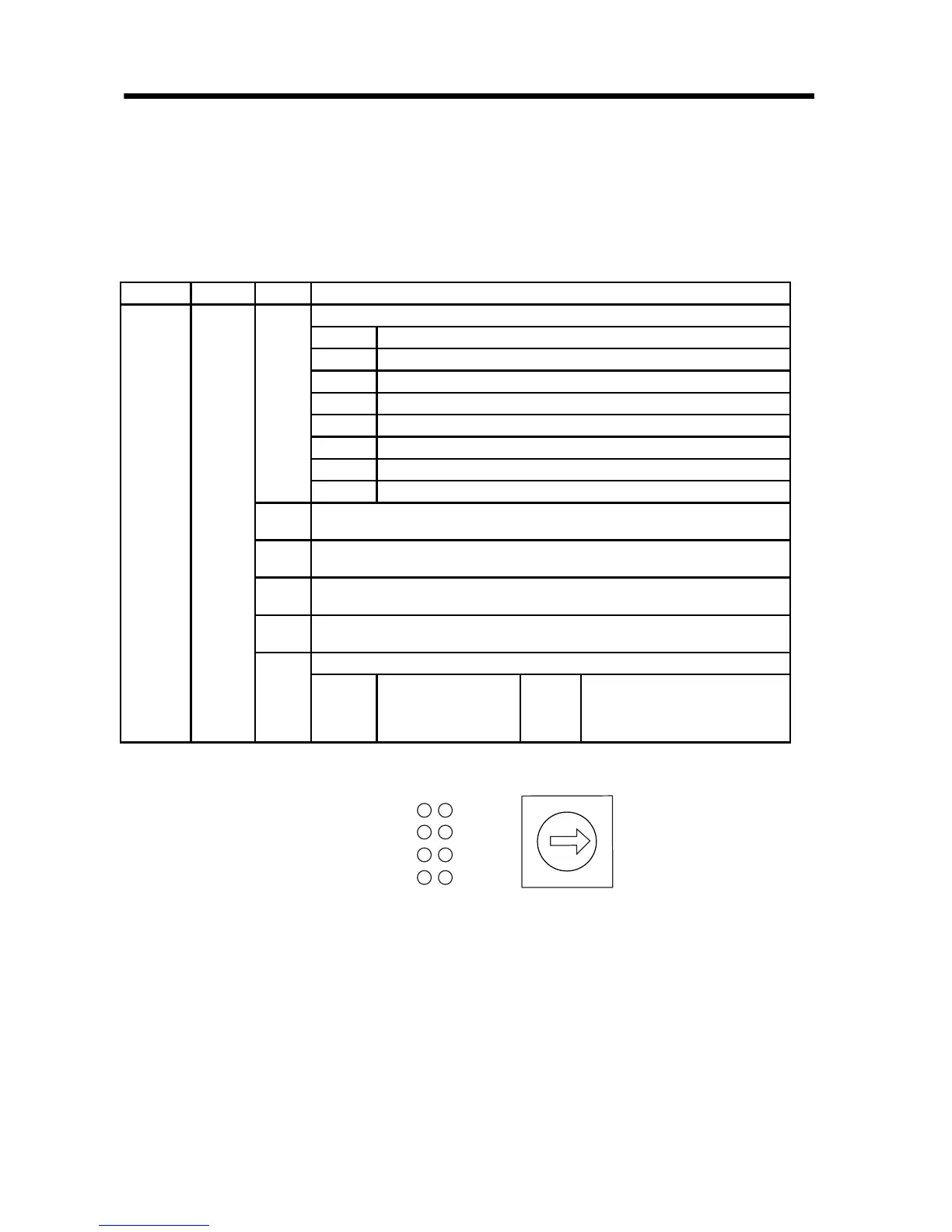
The LIO-04/05 Module status display the LED indicators (LD1 to
LD8) change based on the SW1 rotary switch setting. The following
table shows the ON/OFF indicator display for digital input and digital
output.
Indicator Color SW1 Status when Lit
LD1 to
LD8
Green
0
Board Status Indicators
LD1 Normal operation: Lit, Error: Not lit
LD2 DI_00 to DI_07 status. Lit when any digital input is turned ON.
LD3 DO_00 to DO_07 status. Lit when any digital output is turned ON.
LD4 Pulse A/B input. Lit when phase A/B is turned ON.
LD5 Normal operation: Lit, Error: Not lit
LD6 DI_08 to DI_15 status. Lit when any digital input is turned ON.
LD7 DO_08 to DO_15 status. Lit when any digital output is turned ON.
LD8 Pulse Z input. Lit when phase Z is turned ON.
1
Digital input indicators: When DI_00 to DI_07 turn ON, corresponding
indicators LD1 to LD8 are lit.
2
Digital input indicators: When DI_08 to DI_15 turn ON, corresponding
indicators LD1 to LD8 are lit.
3
Digital output indicators: When DO_00 to DO_07 turn ON, corresponding
indicators LD1 to LD8 are lit.
4
Digital output indicators: When DO_08 to DO_15 turn ON, corresponding
indicators LD1 to LD8 are lit.
5
PI Input Indicators
LD1
LD2
LD3
LD4
Pulse A input
Pulse B input
Pulse Z input
LD5
LD6
LD7
LD8
Coincidence detection
Phase-Z latch
Digital input latch