14.5 LIO-04/05 Modules
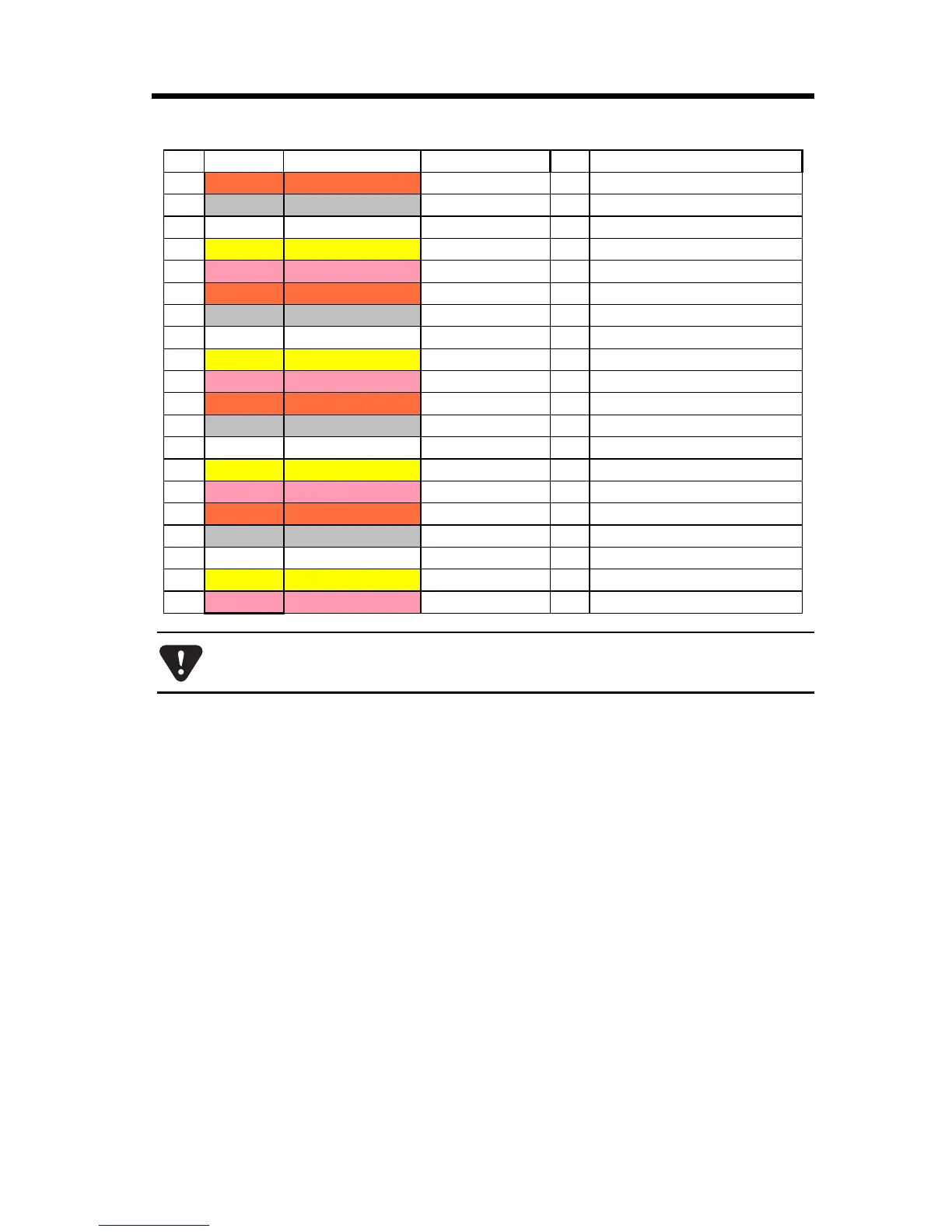
14.5.16 Standard Cable Wiring Table
87
31 Orange — —
N.C.
32
Gray — —
DI_09/25 I/I Digital input 9/25
33 White — —
DI_11/27 I/I Digital input 11/27
34
Yellow — —
DI_13/29 I/I Digital input 13/29
35
Pink — —
DI_15/31 I/I Digital input 15/31
36
Orange — — —
N.C.
37
Gray — — —
DO_01/17 O/O Digital output 1/17
38 White — — —
DO_03/19 O/O Digital output 3/19
39
Yellow — — —
0V_1/3 P/P Digital Output 0VDC common 1/3
40
Pink — — —
+24V_1/3 P/P Digital Output 24V supply 1/3
41
Orange — — — Continuous
DO_05/21 O/O Digital output 5/21
42
Gray — — — Continuous
DO_07/23 O/O Digital output 7/23
43 White — — — Continuous
N.C.
44
Yellow — — — Continuous
DO_09/25 O/O Digital output 9/25
45
Pink — — — Continuous
DO_11/26 O/O Digital output 11/26
46
Orange ————————
0V_2/4 Digital Output 0VDC common 2/4
47
Gray ————————
+24V_2/4 Digital Output 24V supply 2/4
48 White ————————
DO_13/29 O/O Digital output 13/29
49
Yellow ————————
DO_15/31 O/O Digital output 15/31
50
Pink ————————
N.C.
Columns “Signal Name”, “I/O”, and “Function” display the values for connectors
CN1 and CN2 in the format “CN1/CN2” respectively.
Pin Wire Color Markings Signal Name I/O Function