14.6 LIO-06 Module
14.6.4 Option Board Specifications
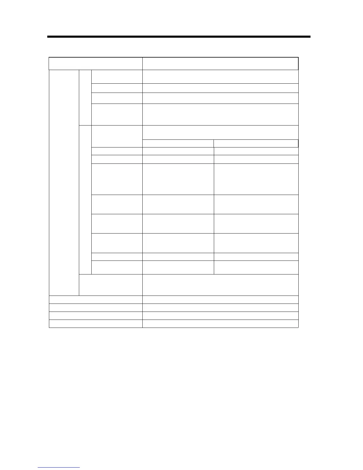
94
Item Specification
Encoder
Input
Encoder Input
Number of
Channels
1
Input Method
5V Differential
Max Frequency 4MHz quadrature
Isolation Non-isolated
Counting System
A/B Phase
Pulse/Direction
UP/DOWN Counter
Latch Input
Number of Input
Circuits
2 (C-Phase latch or digital input latch)
The digital input latch is used in conjunction with DI-01 on pin 39.
C-Phase Latch Digital Input Latch
Input Method Source Photocoupler I/F Sink/Source Photocoupler I/F
Isolation Photocoupler Isolation Photocoupler Isolation
Input Voltage
24VDC±20%
12VDC±20%
5VDC±20%
24VDC/12VDC/5VDC are
switched by connector wiring
DC24V±20%
Input Current
DC24V: 11mA (TYP)
DC12V: 12mA (TYP)
DC5V: 13mA (TYP)
4.1mA (TYP)
ON Voltage
DC24V: 17V Min
DC12V: 9V Min
DC5V: 3.9V Min
15V Min
OFF Voltage
DC24V: 1.6V Max
DC12V: 1.1V Max
DC5V: 0.9V Max
5V Max
Response Time 1s Max 60s Max
Minimum ON Pulse
Width
1s60s
COIN Output
1, digital output
Used together with DO-07 (software switching)
Current Consumption
5V, 1A Max
Hot Swapping (Modules)
Not Possible
Connector
CN1: Digital I/O, Analog I/O, Encoder Input
Indicators
RUN (Green), ALM (Red)