10.2 Motor Rotation Direction
10-3
10
SERVOPACK with Semi-closed Loop Control for Rotary Motors
10.2 Motor Rotation Direction
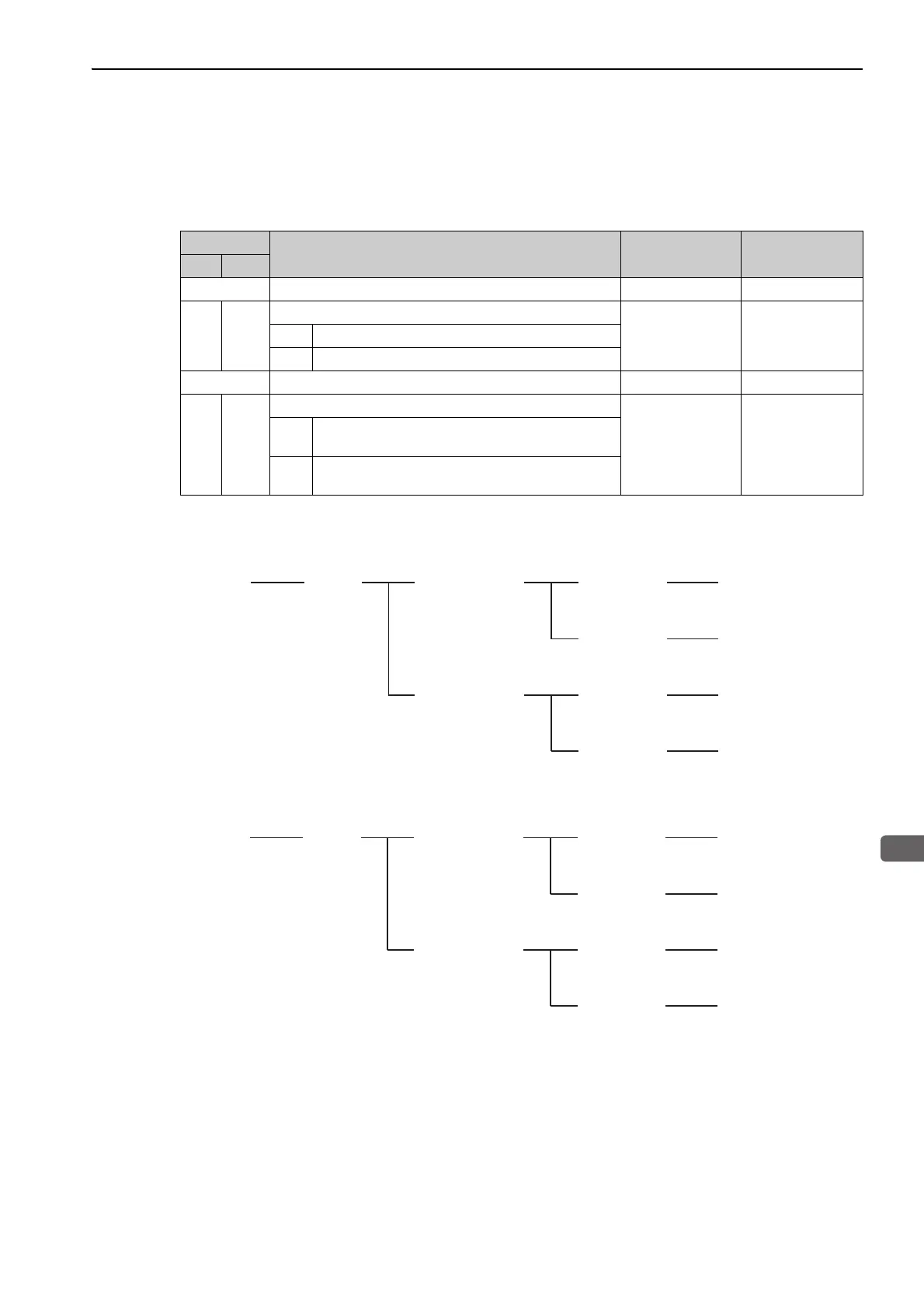
The relationship between feedback position and motor magnetic pole position is dependent on the mounted
conditions. So, the parameters below are used for the coordination.
Parameter Setting
Note: Please make sure Pn080.1 is set according the above diagram. Otherwise motor malfunction may occur.
Parameter
Function Default Value When enabled
No. Dig.
Pn000 Application Function Select Switch 0 - -
0
Direction Selection
0 After restart0 Forward command for counterclockwise rotation
1 Forward command for clockwise rotation
Pn080 Application Function Select Switch 80 - -
1
Motor Phase Selection
0 After restart
0
Sets positive position feedback as phase sequence of
U, V, W
1
Sets negative position feedback as phase sequence of
U, V, W
U -> V -> W
(U -> W -> V)
Pn000.0 = 0
Pn080.1 = 0
Pn000.0 = 0
Pn080.1 = 1
Pn000.0 = 1
Pn080.1 = 1
Pn000.0 = 1
Pn080.1 = 0
U -> W -> V
(U -> V -> W)
U -> V -> W
(U -> W -> V)
Un00D increase
(Un00D decrease)
Available
(Pn080.0 = 0)
Forward
(Reverse)
Un00D decrease
(Un00D increase)
U -> W -> V
(U -> V -> W)
Hall Sensor
Command
Desired Direction
Monitor Feedback
Pulse Counter
Monitor Hall
Sensor (Un011) Parameter Setting
CCW
(CW)
Pn000.0 = 0
Pn080.1 = 0
Pn000.0 = 1
Pn080.1 = 1
Pn000.0 = 0
Pn080.1 = 1
Pn000.0 = 1
Pn080.1 = 0
CW
(CCW)
CCW
(CW)
Un00D increase
(Un00D decrease)
Not available
(Pn080.0 = 1)
Forward
(Reverse)
Un00D decrease
(Un00D increase)
CW
(CCW)
Hall Sensor
Command
Desired Direction
Monitor Feedback
Pulse Counter
Visual Check
Rotation of Shaft Parameter Setting

 Loading...


