10 SERVOPACK with Semi-closed Loop Control for Rotary Motors
10-2
10.1 Magnetic Pole
For driving third party motors and some Sigma-1 motors, the magnetic pole should be coordinated. The
parameters in the following table are used for that.
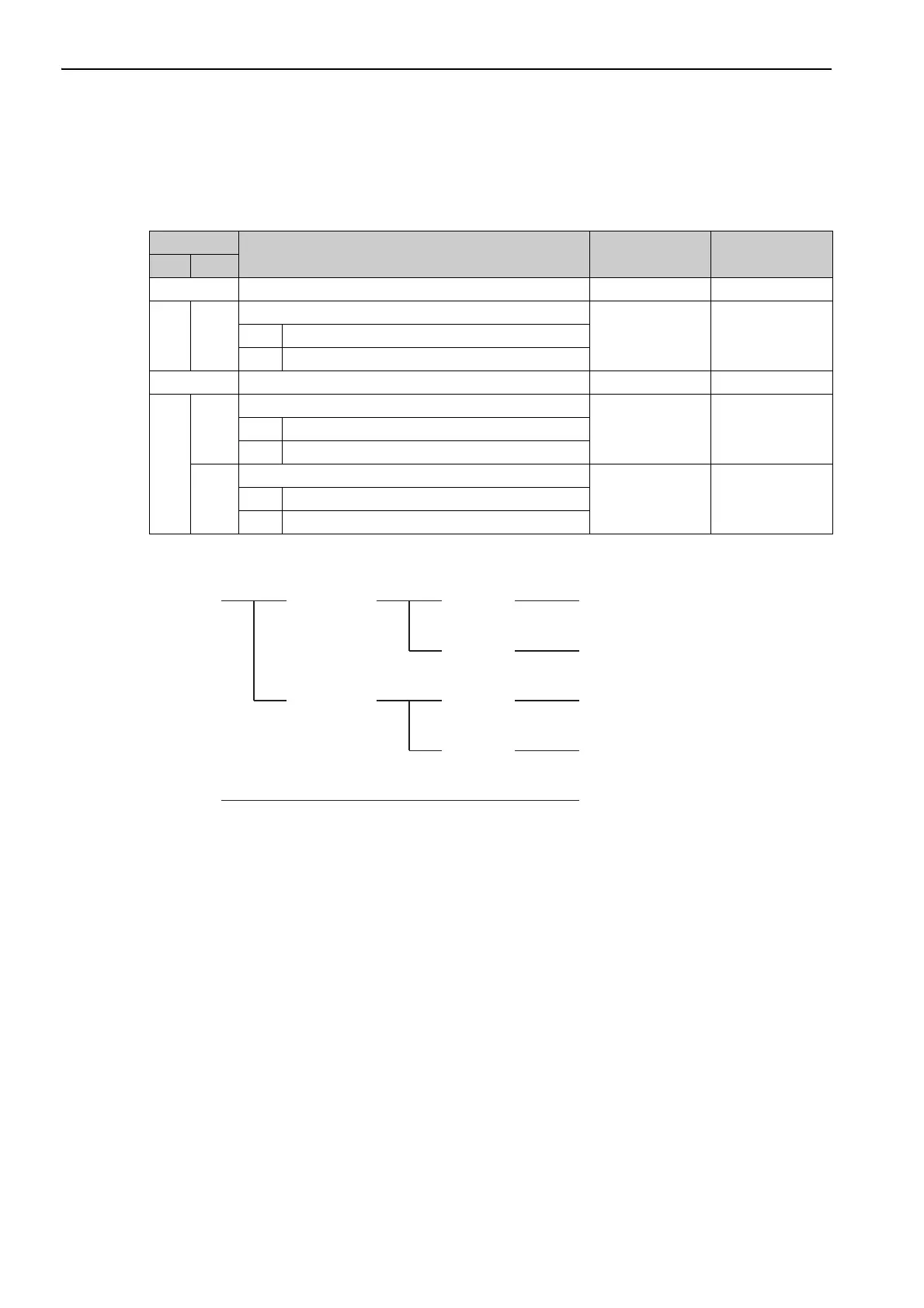
Parameter Setting
Note 1. If the relation between origin and U phase position is not sure, please set Pn081.2 to 1. Otherwise motor malfunc-
tion may occur.
2. In case the hall sensor is not available refer to chapter 10-4.
Parameter
Function Default Value When enabled
No. Dig.
Pn080 Application Function Select Switch 80 - -
0
Hall Sensor Selection
0 After restart0 Enables hall sensor
1 Disables hall sensor
Pn081 Application Function Select Switch 81 - -
2
Coordination Setting between Origin and U-phase position
0 After restart0 Both positions are same
1 The positions are different
3
Hall Sensor Signal Inversion
0 After restart0 Does not inverse the signals (Pos-Logic)
1 Inverses the signals (Neg-Logic)
Positive logic Pn080.0 = 0
Pn081.2 = 0
Pn081.3 = 0
Pn080.0 = 0
Pn081.2 = 0
Pn081.3 = 1
Pn080.0 = 0
Pn081.2 = 1
Pn081.3 = 0
Pn080.0 = 0
Pn081.2 = 1
Pn081.3 = 1
Pn080.0 = 1
Pn081.2 = 0
Pn081.3 = 0
Negative logic
Positive logic
Same positionAvailable
Not available
Different Position
Negative logic
Hall Sensor Origin and U-phase Hall Sensor Signal Parameter Setting

 Loading...


