11 SERVOPACK with Semi-closed Loop Control for Linear Motors
11-4
11.3 Pole Detection Functionality
When using a linear motor without pole sensor, the pole detection should be executed. Make sure the follow-
ing conditions are satisfied when executing the function.
1. There is no danger when the linear motor moves approximately 10 mm. In case the function
fails, the linear motor may move approximately 50 mm.
2. The encoder period is within 100 µm. (Within 40 µm is recommended when using an
incremental encoder.)
3. Minimum unequal external force on the linear motor (5% of the rated force maximum is
recommended).
4. The mass ratio is within 50 times.
5. On a horizontal axis.
6. Friction on the guide is a few percentages of the rated force (air slide not used).
Note 1. The linear motor is turned ON during the function. Take measures to avoid electric shock.
2. The linear motor will make large movements during detection. Take the machine’s range of motion into consider-
ation and do not stand near any moving parts.
3. The function depends on many factors such as cable tension, mass ratio and friction. If any error occurs because
of one of these factors the function may fail.
(1) Requirements that Enable the Function
The function is enabled by the following settings:
1. The parameter Pole Sensor Selection Pn080.0 is set to disable pole sensor Pn080.0 = 1.
2. The main power is supplied.
3. No alarms occur.
4. Hard wire base block is not active.
5. The parameter Writing Prohibited Setting Fn010 is not set to prohibit writing.
6. The SEN signal is turned ON in case of an absolute encoder.
(2) Execution of the Function with Analog Voltage and Pulse Train Model
Input Signal Through CN1 connector
Factory-set Input Signal Allocations
If the factory settings are used to allocate the input signals (Pn50A.0 = 0), the function will start when the
Servo On signal (/S-ON) is ON, and the Servo Ready signal (/S-RDY) will be ON after the function has been
completed.
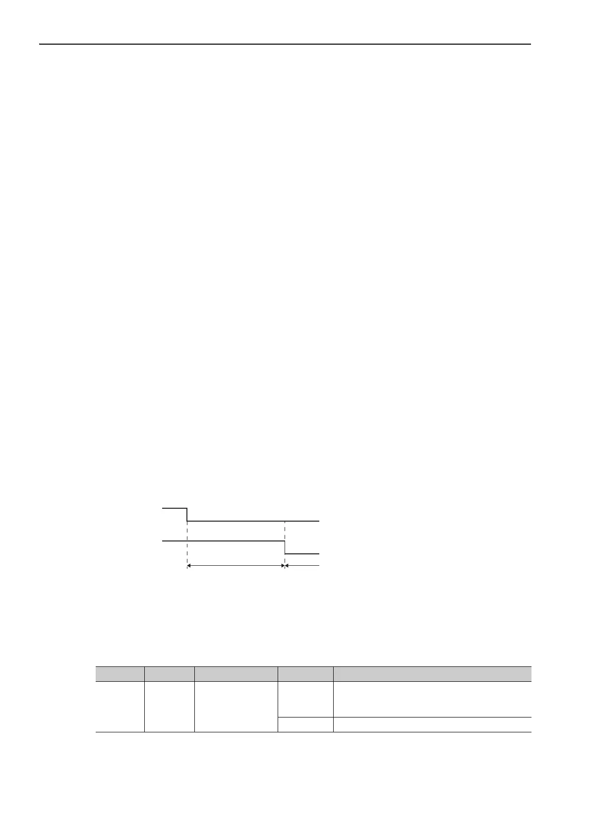
Changing Input Signal Allocations
The function signal (/P-DET) must be allocated under the following conditions:
• When designing a sequence for the host controller in which the Servo Ready signal is monitored and then
the Servo ON signal is output.
/S-ON input
(/P-DET)
Polarity detection is
being executed.
Status display: P-dt
Polarity detection competed.
Normal operation of servo motor.
/S-RDY output
Type Name Connector Pin No. Setting Description
Input /S-ON CN1-40
ON
Motor power is ON.
The function is executed only once then the motor
will be ready for operation (/S-RDY signal is ON).
OFF Motor power is OFF.

 Loading...


