5 Operation
5.4.1 Basic Settings for Position Control Mode
5-36
The built-in power supply of the SERVOPACK can be used. With an external power supply, a photocoupler
isolation circuit will be used. A non-isolated circuit will be used if the built-in power supply is used.
∗ represents twisted-pair wires.
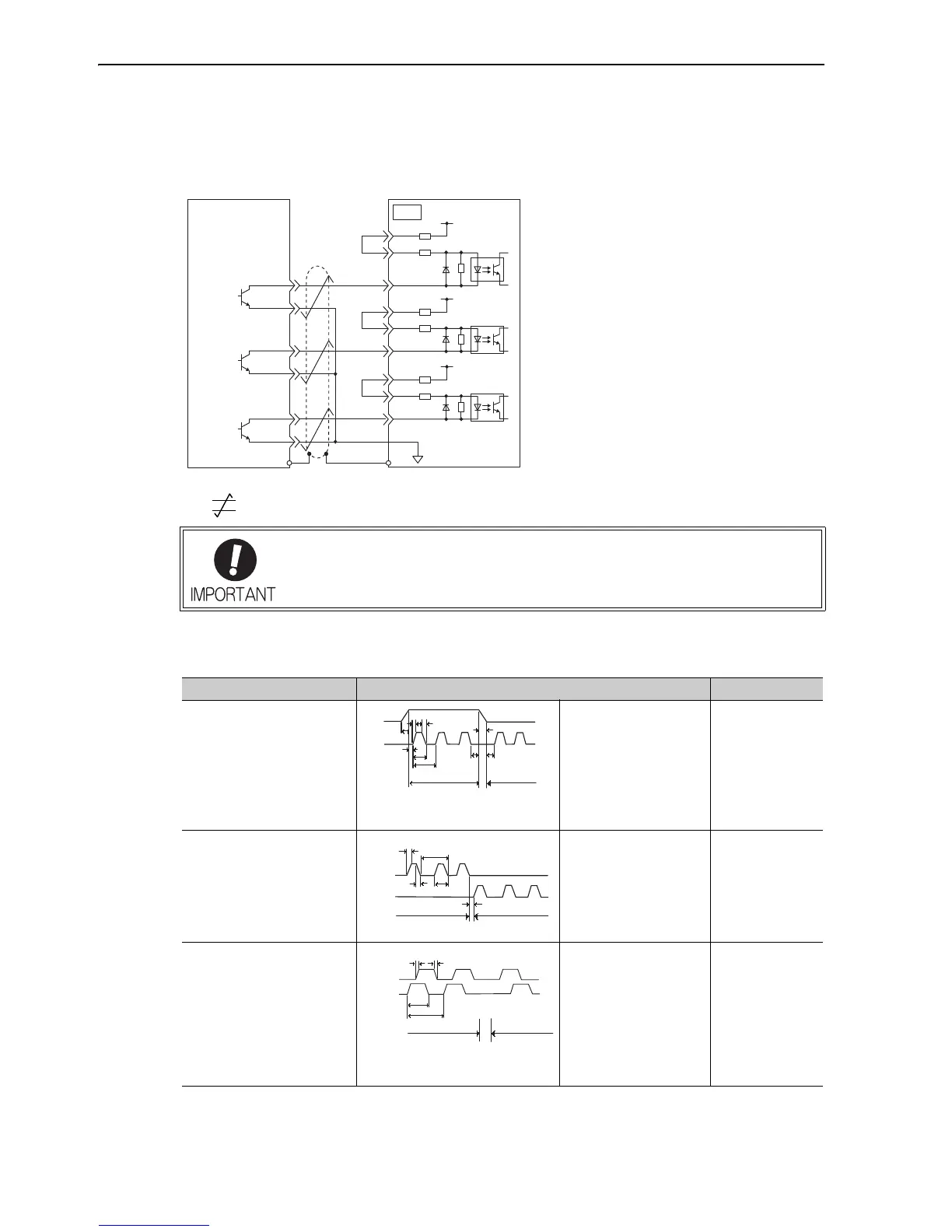
(4) Electrical Specifications for Pulse Train Reference
Forms of pulse train references are as shown below.
∗ Maximum reference frequency by each multiplier are as follows.
×1 input pulse multiplier: 1 Mpps
×2 input pulse multiplier: 1 Mpps
×4 input pulse multiplier: 1 Mpps
• Use a shielded cable for I/O signals and ground both ends of the shield.
• Connect the shield at the SERVOPACK to the connector shell so that the shield will
be connected to the frame ground (FG) through the connector.
Pulse Train Reference Form Electrical Specifications Remarks
Sign + pulse train input
(SIGN + PULS signal)
Maximum reference fre-
quency: 4 Mpps
(In case of open-collector
output, maximum refer-
ence frequency: 200 kpps)
t1, t2, t3, t7 ≤ 0.025 μs
t4, t5, t6 ≥ 0.5 μs
τ ≥ 0.125 μs
T-τ = 0.125 μs
Sign (SIGN)
H = Forward
reference
L = Reverse
reference
CW pulse + CCW pulse
Maximum reference fre-
quency: 4 Mpps
(In case of open-collector
output, maximum refer-
ence frequency: 200 kpps)
t1, t2 ≤ 0.025 μs
t3 ≥ 0.5 μs
τ ≥ 0.125 μs
T-τ = 0.125 μs
Two-phase pulse train with
90° phase differential
(phase A + phase B)
Maximum reference fre-
quency: 1 Mpps*
(In case of open-collector
output, maximum refer-
ence frequency: 200 kpps)
t1 ≤ 0.1 μs
t2 ≥ 0.1 μs
τ ≥ 0.5 μs
T-τ = 0.5 μs
Reference pulse
form is set with
Pn200.0.