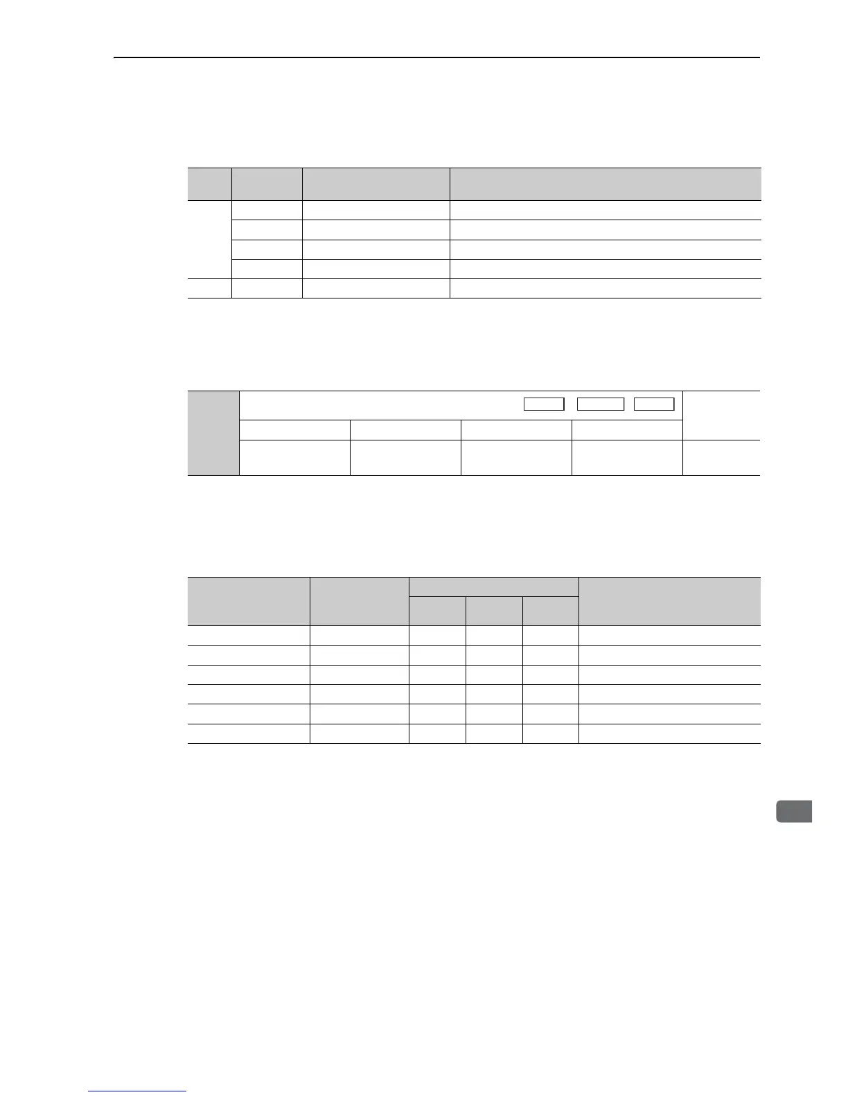
(3) When Using an Absolute Encoder
When absolute encoder is used, add the following signals.
∗ SG (CN1-1, 2): Connect to 0 V on the host controller.
5.3.7 Encoder Output Pulse Setting
Set the encoder output pulse using the following parameter.
Pulses from the encoder per revolution are divided inside the SERVOPACK by the number set in this parame-
ter before being output. Set according to the system specifications of the machine or host controller.
According to the encoder resolution, the number of encoder output pulses are limited. Set the encoder output
pulses (Pn212) by the following setting unit.
Note 1. The setting range varies with the encoder resolution for the servomotor used.
A parameter setting error alarm (A.041) will occur if the setting is outside the allowable range or does not satisfy
the setting conditions.
Pn212 = 25000 (P/Rev) is accepted, but
Pn212 = 25001 (P/Rev) is not accepted. The alarm A.041 is output because the setting unit differs from that in
the above table.
2. The upper limit of the pulse frequency is approx. 1.6 Mpps.
The servomotor speed is limited by the setting value of the number of the output pulse for Pn212.
An overspeed alarm (A.511) will occur if the motor speed exceeds the upper limit specified in the above table.
Type
Signal
Name
Connector Pin Number Name
Input
SEN CN1-4 SEN Signal Input
SG CN1-2 Signal Ground
BAT (+) CN1-21 Battery (+)
BAT (-) CN1-22 Battery (-)
Output SG* CN1-1, CN1-2 Signal Ground
Pn212
Encoder Output Pulses
Classification
Setting Range Setting Unit Factory Setting When Enabled
16 to
1073741824(2
30
)
1 P/Rev 2048 After restart Setup
Speed