4.3.1 Inspecting Connection and Status of Input Signal Circuits
Check the items in step 1 before trial operation of the servomotor under speed control and position control ref-
erences from the host.
Check the connection and status of input signals using the following procedure.
Step Operation Reference
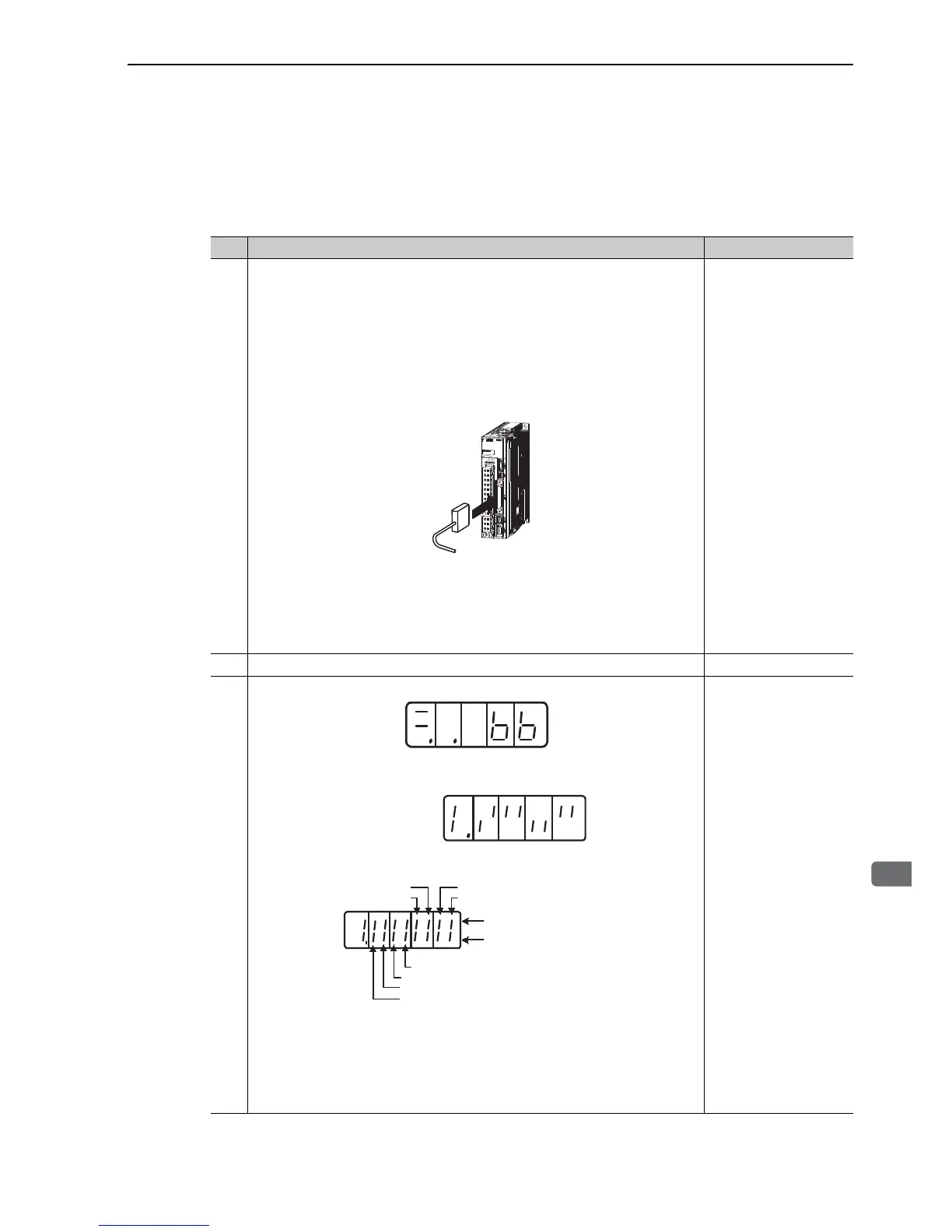
1
Connect the necessary input signal circuits to the I/O signal connector (CN1) under
the following conditions.
• It must be possible to input servo ON input signal (/S-ON).
• The forward run prohibited (P-OT) and reverse run prohibited (N-OT) input sig-
nals must be ON (L level) (i.e., the servomotor must be able to run in forward and
reverse).
Settings: CN1-42 and CN1-43 must be ON (L level) or Pn50A.3 and Pn50B.0
must be set to 8.
Note: Return the settings to the previous ones after completing trial operation.
• Make sure that there is no reference input.
<Note>
• If Pn002 is set to n. 1, the absolute encoder can temporarily be used as an
incremental encoder, which makes it possible to perform trial operation of the ser-
vomotor without Fn008 and SEN signal settings
Connect a safety device to CN8 when using the safety function.
For the connecting method, refer to (1) Connecting a Safety Device.
Refer to the following
connection diagrams.
3.2.4 Example of I/O Sig-
nal Connections in Speed
Control
3.2.5 Example of I/O Sig-
nal Connections in Posi-
tion Control
3.2.6 Example of I/O Sig-
nal Connections in Torque
Control
5.9.1 Encoder Resolutions
5.11 Safety Function
3.2.3 Safety Function Sig-
nal (CN8) Names and
Functions
2 Connect the connector of the host and the I/O signal connector (CN1) together.
3
Turn ON the power and make sure that the panel operator display is as shown below.
Check the input signal using the Un005 (input signal monitor) from the panel opera-
tor. If the display is not same as shown below, correct the input signal setting.
Note:
• If an absolute encoder is being used, turn ON the SEN signal. The servo will not
turn ON when only servo ON signal (/S-ON) is input.
• When the SEN signal is checked in monitor mode, the top of the LED will light
because the SEN signal is high when ON.
• Input signals can be also checked using wiring check function of SigmaWin+.
8.4 Monitoring Input Sig-
nals
3.3.1 Input Signal Alloca-
tions