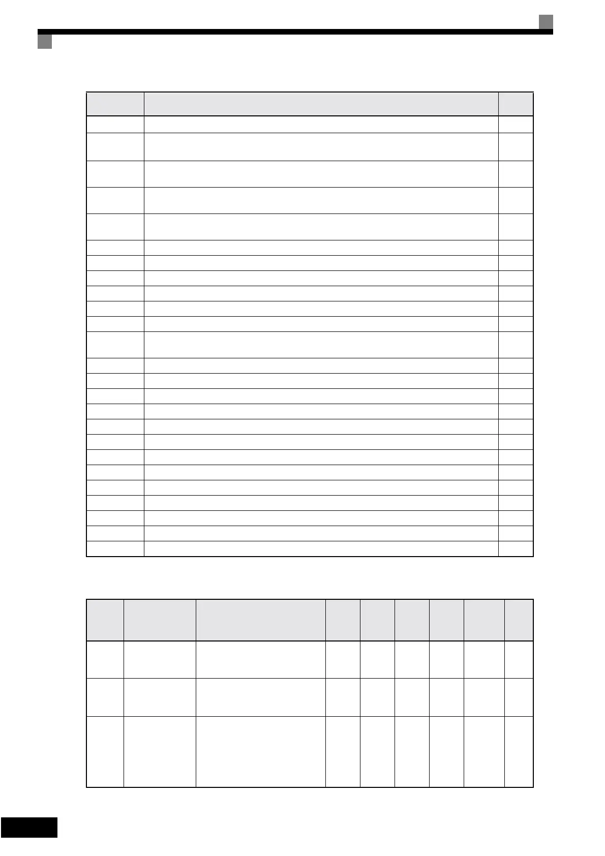
5-28
Analog Inputs: H3
2
f
ref
/f
out
agree 1 (detection width L4-02 is used.)
6-27
3
f
ref
/f
set
agree 1 (ON: Output frequency = ±L4-01, with detection width L4-02 used and during
frequency agree)
6-27
4
Frequency detection 1 (ON: +L4-01 ≥ output frequency ≥ -L4-01, with detection width L4-02
used)
6-27
5
Frequency detection 2 (ON: Output frequency ≥ +L4-01 or output frequency ≤ -L4-01, with
detection width L4-02 used)
6-27
6
Inverter operation ready
READY: After initialization or no faults
6-64
7 During DC bus undervoltage (UV) detection 6-64
8 During baseblock (NO contact, ON: during baseblock) 6-64
9 Frequency reference source selection (ON: Frequency reference from Operator) 6-64
A Run command source selection status (ON: Run command from Operator) 6-64
B Overtorque/undertorque detection 1 NO (NO contact, ON: Overtorque/undertorque detection) 6-31
C Loss of frequency reference (Effective when 1 is set for L4-05) 6-44
E
Fault (ON: Digital Operator communications error or fault other than CPF00 and CPF01 has
occurred.)
6-64
F Not used. (Set when the terminal is not used.) -
10 Minor fault (ON: Alarm displayed) 6-64
11 Fault reset command active 6-65
12 Timer function output 6-82
17 Overtorque/undertorque detection 1 NC (NC Contact, OFF: Torque detection) 6-31
1A Reverse direction 6-65
1E Restart enabled (ON: Restart enabled) 6-45
1F Motor overload (OL1, including OH3) pre-alarm (ON: 90% or more of the detection level) 6-33
20 OH pre-alarm (temperature reached L8-02) 6-65
38 Drive enabled 6-65
39 Drive waiting (start delay time b1-11 is active) 6-65
3A During OH and reduced Frequency 6-65
3B RUN command from option card/communications 6-65
Constant
Number
Name Description
Setting
Range
Factory
Setting
Change
during
Opera-
tion
Access
Level
MEMO-
BUS
Register
Page
H3-02
Gain (terminal
A1)
Sets the frequency as a percentage
of themaximum output fre-
quency, when 10 V is input.
0.0 to
1000.0
100.0% Yes A 411H 6-22
H3-03
Bias (terminal
A1)
Sets the frequency as a percentage
of the maximum frequency, when
0 V is inut.
-100.0
to
+100.0
0.0% Yes A 412H 6-22
H3-08
Multi-function
analog input ter-
minal A2 signal
level selection
0: 0 to +10V (11 bit).
2: 4 to 20 mA (9-bit input).
3: 0 to 20 mA (9-bit input)
Switch current and voltage input
using the switch S1 on the control
terminal board.
0, 2, 3 2 No A 417H 6-22
Setting
Value
Function
Page
Artisan Technology Group - Quality Instrumentation ... Guaranteed | (888) 88-SOURCE | www.artisantg.com