1-7
IM AQ1210-01EN
Features
1
1.3 Displaying Measured Data (OTDR)
How to View Optical Pulse Waveforms (TRACE mode)
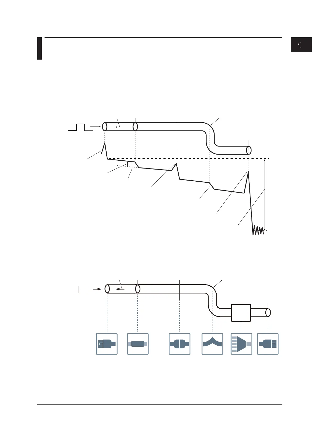
The optical pulse applied to the optical fiber cable is reflected at different points of the optical fiber such
as its connections, bent sections, and the open end of the fiber. These sections generate loss. The
measured result is displayed as a waveform that has distance represented in the horizontal direction
and loss level represented in the vertical direction. On the waveform, detected losses or reflections are
known as events.
Incident ray Backscatter Splice
Connector Bend
Open end
Near-end reflection
Splice loss
Approximation line
Reflection caused by a connector
Loss caused by bending
Reflection at the open end (Fresnel reflection)
Dynamic range (SNR = 1)
Optical fiber cable
How to View the Icon Display (MAP mode)
Losses and reflections that occur at connections, bent sections, and open ends are displayed using
icons. Events in the section from the measurement start point to the open end are displayed in order
from the start point.
Splice loss Return loss Bending loss Splitter End point
(Fresnel
reflection)
Start point
(Near-end
reflection)
Incident ray Backscatter Splice
Connector Bend
Open end
Splitter
Optical fiber cable
 Loading...