5-5
IM 04L51B01-01EN
Maintenance and Troubleshooting
5
Calibrating AO Modules
Required Instruments
To calibrate AO modules, you need calibration instruments with the following specifications
and accuracy.
Recommended Instruments
• Resistance standard : Resisitance value: 600 Ω or less
Accuracy: ±0.01% or more
Allowable power: 0.25 W or higher
Temperature coefficient: 5ppm/°C or less
• Digital Multimeter : Accuracy: ±0.01% or more
For information on purchasing these calibration instruments, contact the YOKOGAWA dealer that you
purchased the GX/GP from.
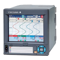
Calibration Procedure
1
Wire the GX/GP and the calibration instruments as shown in the following figure, and
adequately warm up the instruments (the warm-up time of the GX/GP is at least 30
minutes).
2
Check that the operating environment such as ambient temperature and humidity is
within the standard operating conditions (see “General Specifications”).
3
Set the range type to Manual and the range to 4-20mA.
4
Manually output 4 mA and 20 mA, and determine the error from the measured values.
For measurements using voltage, the error is determined from the difference between
the measured value and the digital multimeter value. If the error does not fall within
the accuracy range of the specifications, servicing is required. Contact your nearest
YOKOGAWA dealer.
–
CH1 output terminal
+
Digital multimeter
.
Resistor
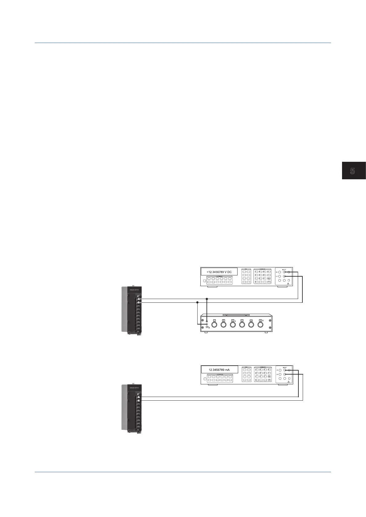
–
+
CH1 output terminal
Digital multimeter
Current input terminal
.
Wiring for current measurement
Wiring for voltage measurement
Calibrating PID Modules
For input calibration, refer to the AI module calibration. For output calibration, refer to the AO
module calibration.
For details on wiring, see “Installation and Wiring” in the First Step Guide (IM 04L51B01-
02EN).
5.1 Maintenance

 Loading...