4
All Rights Reserved. Copyright © 2014, Yokogawa Electric Corporation
GS 04L53B00-01EN
June. 14, 2017-00
Normal Operating Conditions
• Powersupplyvoltage:100to240VAC±10%
• Powersupplyfrequency:50/60Hz±2%
• Ambienttemperature:0to50°C
• Ambienthumidity:20to80%RH(at5to40°C)
(no condensation)
• Magneticeld:400A/morless(DCand50/60
Hz)
• Vibration:
5≤f<8.4Hzamplitude3.5mm(peak)
8.4≤f≤160Hzacceleration9.8m/s
2
or less
• Shock(IEC-60068-2-27):
Non-energization,500m/s
2
orless,approximate
10ms,6directions(±X,±Y,±Z)
• Mountingposition:Canbeinclinedupto30
degreesbackward.Leftandrighthorizontal
wheninstallingthepanelmountandwallmount.
• Altitude:2000morless
• Installationlocation:Indoors
• Warm-uptime:Atleast30minutesafterpower
on
Transport and Storage Conditions
• Ambienttemperature:–25to60°C
• Ambienthumidity:5to95%RH(no
condensation)
• Vibration:10to60Hz,4.9m/s
2
maximum
• Shock:392m/s
2
maximum(inpackaged
condition)
Effects of Operating Conditions
• Powersupplyvariation:Shallsatisfythe
accuracyspecicationintherangeof90to132
VACor180to250VAC(frequency:50/60Hz).
Powersupplyfrequencyuctuation:Shallsatisfy
theaccuracyspecicationintherangeofrated
supplyfrequency+/-2Hz(power-supplyvoltage:
100VAC).
GX90EX SPECIFICATIONS
Communication Functions
CommunicationbetweenGX/GPandGX60,
betweenGX60s,betweenGMmainunitand
subunit,betweenGMsubunitsviadedicated
communicationnetwork.
• Baudrate:10Base-T/100Base-TX(Auto)*1
• Numberofports:2
• Connectioncable:STPcable,CAT5orgreater
• Inter-moduleconnection:Cascadeconnection
(Ring connection is disabled.)
• Maximumcommunicationdistance:100m*2
• Connector:RJ-45
*1Canbexedto10Base-TbyDIPswitchsettings.
*2DistanceextensionthroughHUBconnectionor
LAN repeaters is not possible.
Display Functions
• SystemstatusLEDindicators:
RDY(green):LightsupwhentheCPUisrunning
normally.
MAIN(green):Turnsoninmastermodeandoff
inslavemode.
FAIL(red):Lightsupwhenasystemerror
occurs.
• 7-segmentLEDindicator:Indicatesaunit
numberoroperationerror.
• EthernetstatusindicatorLED:LINKACT(green),
SPEED(orange)
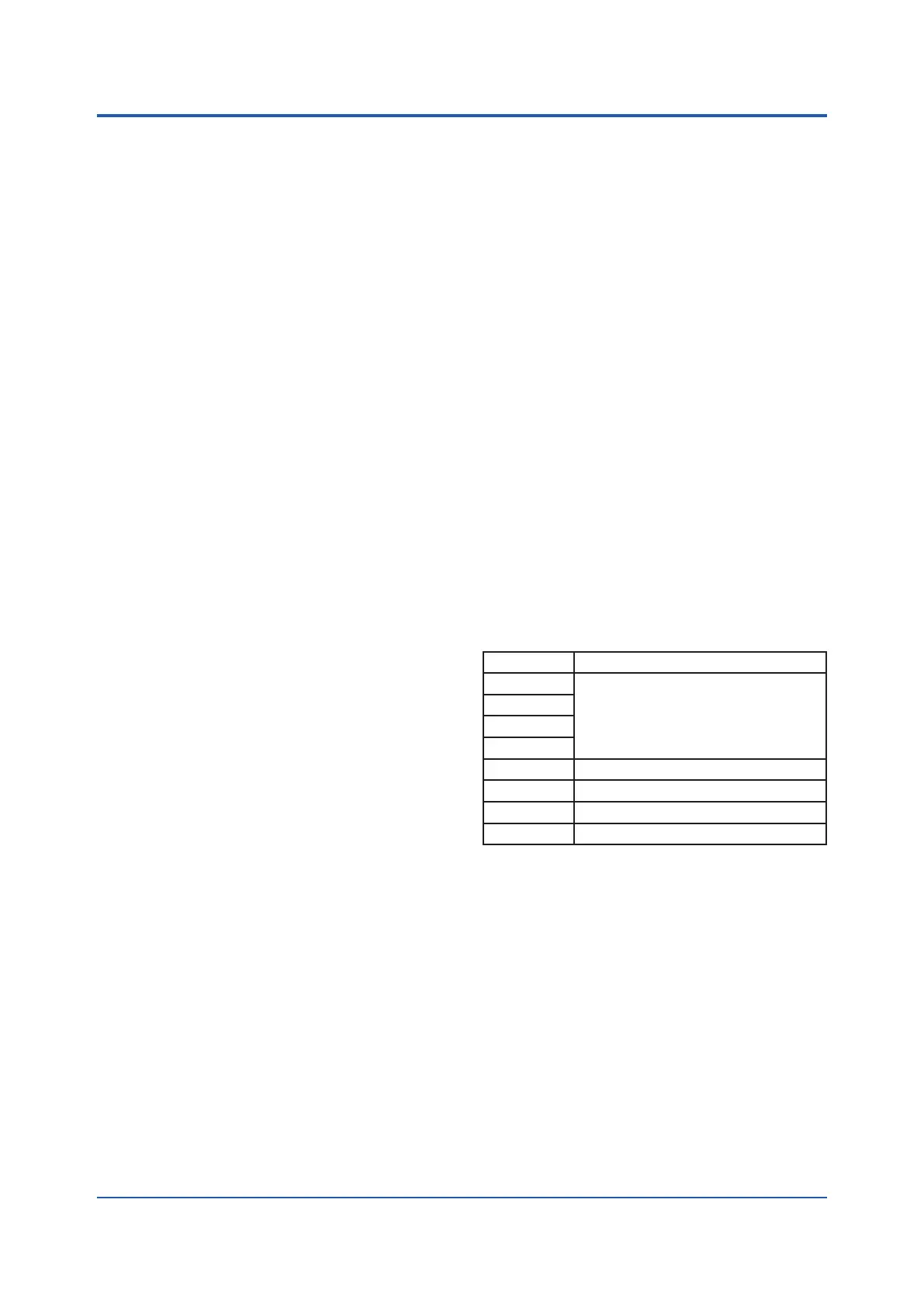
Address Setting Functions
Switchsettings:
Switch No. Descriptions
1 Forunitnumbersetting
2
3
4
5 -
6 -
7 10 Mpbs/100 Mbps switching
8 MASTER/SLAVEswitching
Master / Slave Functions
Canbesettomastermode(wheninstalledintheGX/
GPorGMmainunit),orslavemode(wheninstalled
intheGX60orGMsubunit)usingtheDIPswitches.
10 Mbps Fixed Mode
Canbesettothe10MbpsxedmodeusingtheDIP
switches.
Mounting
CanbemountedintheGX/GP,GX60,GMmainunit,
and GM sub unit.
• Mountingposition:
GX10/GP10:Slot2
GX20/GP20:Slot9
GX60:EXTslot
GMmainunit:Leftmostposition
GMsubunit:Nexttothepowersupplymodule

 Loading...