Interface Connector Wiring
153
Serial Port Interface
Zebra Auto-Detecting DTE and DCE for 9-Pin RS-232 Interface
Important • The maximum current available through the serial port, USB port or both will not exceed a total of 0.75
Amps.
When XON/XOFF handshaking is selected in the printer driver, data flow is controlled by the ASCII control
codes DC1 (XON) and DC3 (XOFF). The DTR control lead will have no effect.
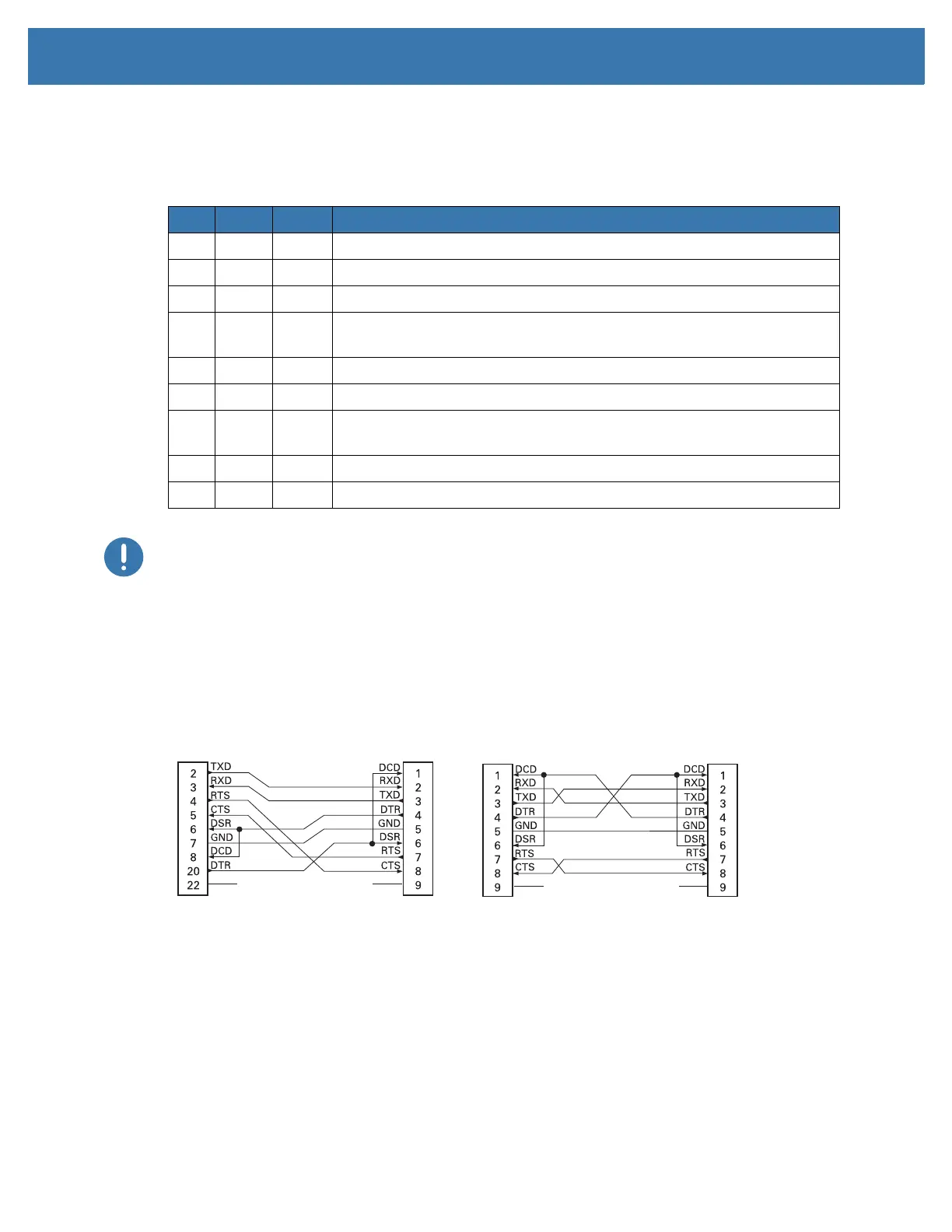
Connecting the Printer to a DTE Device
Interconnecting to DTE Devices — The printer is configured as data terminal equipment (DTE). To
connect the printer to other DTE devices (such as the serial port of a personal computer), use an RS-232
null modem (crossover) cable.
Pin DTE DCE Description (DTE)
1 — 5V Not used
2 RXD TXD RXD (receive data) input to the printer
3 TXD RXD TXD (transmit data) output from the printer
4 DTR DSR DTR (data terminal ready) output from the printer -- controls when the
host may send data
5 GND GND Circuit ground
6 DSR DTR DSR (data set ready) input to the printer
7 RTS CTS RTS (request to send) output from the printer -- always in the ACTIVE
condition when the printer is turned on
8 CTS RTS CTS (clear to send) - Not used by the printer
9 5V — +5 V @ 0.75 A - FET Circuit current limited
DB-25S
Connector
to DTE Device (PC)
DB-9P
Connector
to Printer
DB-9P
Connector
to Printer
DB-9S
Connector
to DTE Device (PC)