Axiovert 40
B 46-0031 e 11/03 3Ć11
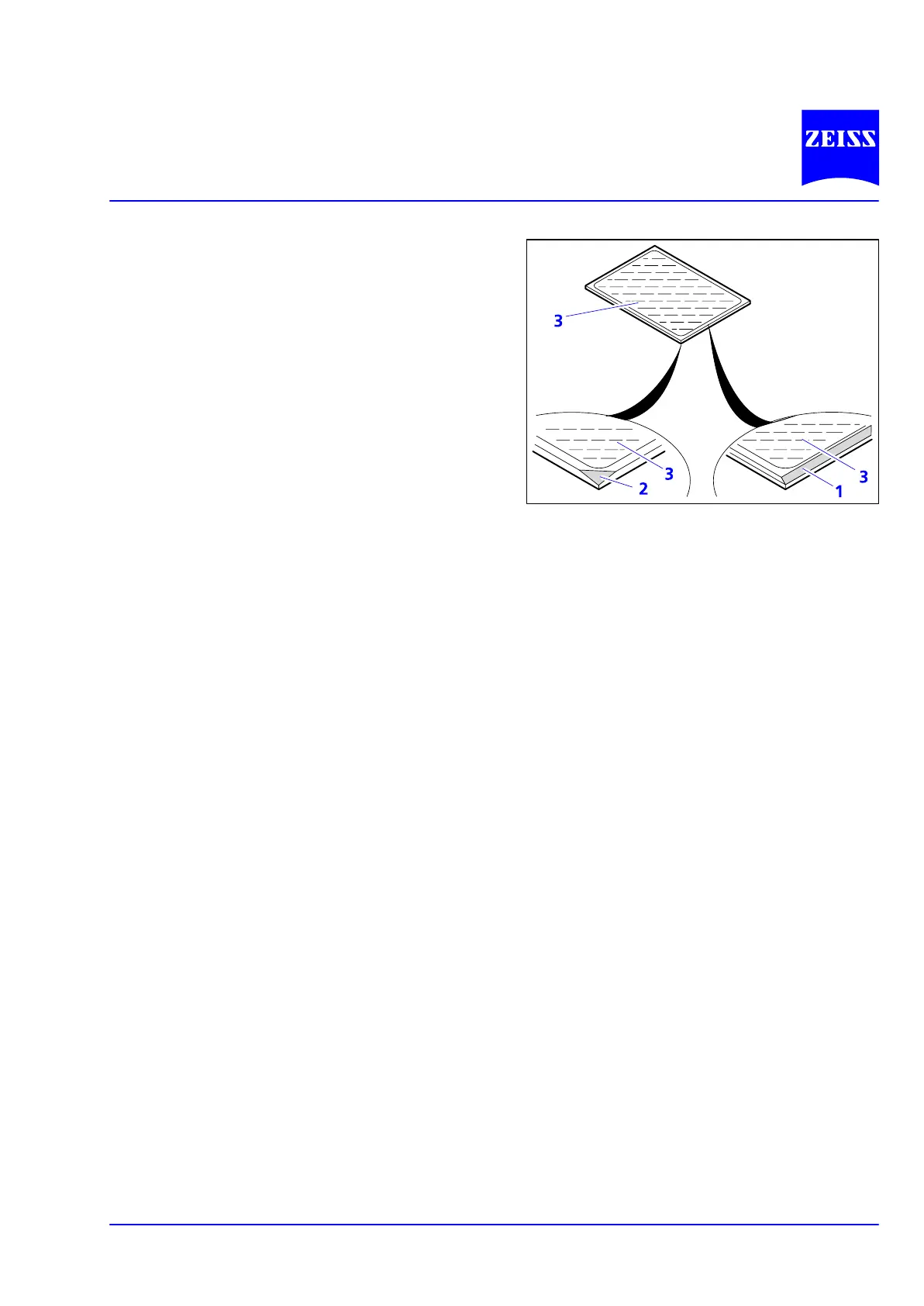
NOTE The reflective (coated) side (3Ć12/ā3)
of the dichroic beam splitter is proĆ
vided with a beveled edge (3Ć12/ā1) or
corner (3Ć12/ā2).
• Put the excitation half (3Ć11/ā1) onto the emisĆ
sion half (3Ć11/ā4) of the module (holding eleĆ
ments 3Ć11/ā5b and eyes 3Ć11/ā5a interlock). HoldĆ
ing both halves together, turn them over in
mounting position again.
• Reinsert the slotted screws and tighten them.
• Finally affix the adhesive label with the designaĆ
tion of the filter combination to the side of the
module.
• Insert the reflector module FL P&C into the 3-posiĆ
tion reflector slider P&C as described above.
Fig. 3Ć12 Marking of dichroic beam splitter