Programming - Serial Port
100 025-9567E
The DTR (data-terminal-ready) and RTS (request-to-send) signals are passively pulled to +12
volts via 330 resistors. These connections may be used to provide “space” levels for tying
to other RS-232C signals.
The RS-232C levels sent out the
TX DATA pin are approximately -3.0 volts for a “mark” and
+10 volts for a “space” or “break” level. The acceptable RS-232C levels received at the
RX
DATA
, CTS, and RMT CTL pins are +0.7 to -15 volts for a “mark” level and +1.5 to +15 volts
for a “space” level.
Several of the remote control parameters are programmable. The programmable parameters
are shown below. When in instant call mode these parameters are fixed at: baud = 4800, 1
NUL for new lines, no BEL characters, ignore CTS. Details of these parameters are available
in the subsection “PROGRAMMING SECTION 6 - REMOTE CONTROL SETUP” on page
96.
Baud rate: 4800, 600, or 150
Number of ASCII NUL characters for each new line: 0 to 99
Use of the ASCII BEL character: enable or disable use
Use of the CTS signal: use CTS as a busy or ignore CTS
Polarity of the CTS signal: busy on “space” or “mark” levels
Call logging: disable or enable logging output.
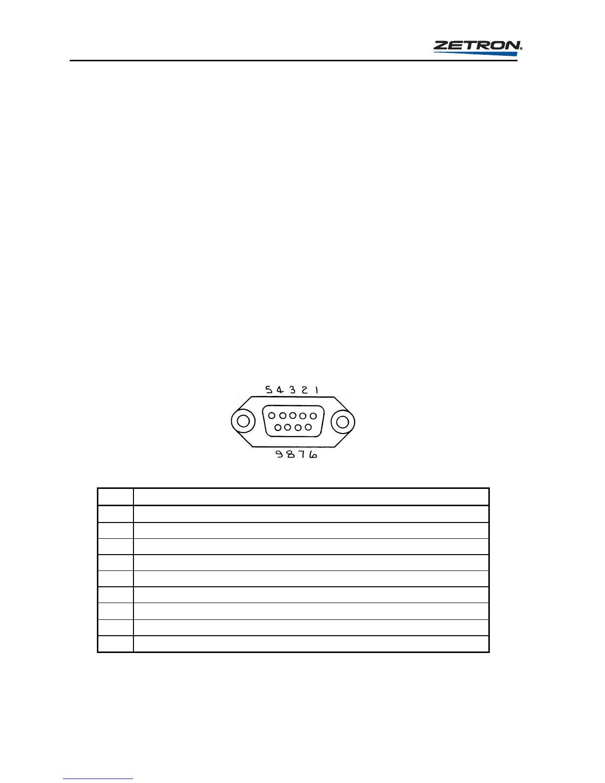
The pin definition of the DE9 computer port connector socket is listed in Table 27.
Table 27. Model 25 Computer Port Pinout
Pin Label/Function
1
DTR (data-terminal-ready) provides “space” (pull-up to +12v via 330)
2 N/C (no connection)
3 TX DATA (transmit data)
4 RX DATA (receive data) “break” resets encoder
5 SIGNAL-GROUND
6 N/C (no connection)
7
RTS (request-to-send) provides “space” (pull-up to +12v via 330)
8 CTS (clear-to-send) also known as “printer busy”
9 RMT-CTL (remote-control) “space” = rmt ctl.