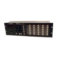
Encoder Installation
025-9567E 45
COMPUTER PORT
The computer port on the Model 25 encoder is compatible with RS-232C signals and uses an
asynchronous ASCII serial communications protocol. The DE9 computer port connector
socket contains four active RS-232C compatible signals;
TX DATA, RX DATA, CTS (clear-
to-send), and
RMT-CTL (remote-control). Other passive signals in the computer port
connector are DTR (data-terminal-ready), and RTS (request-to-send). Of course SIGNAL-
GROUND
is also included in the connector.
The TX DATA and RX DATA are the serial transmit and receive signals. The data signals
communicate in full duplex and use eight bits per ASCII character with one stop bit and no
parity bits. The most significant bit of the eight-bit character is always zero. The baud rate
(bit rate) of the serial data may be one of three programmable rates. One second or more of a
“space” or “break” level on the “RX DATA” pin will cause the encoder to reset.
The CTS input signal may be used to halt the serial transmission from the TX DATA signal if
the signal indicates not-clear-to-send. The CTS signal is most often used by serial printers as
the busy signal. The use and “busy” polarity of this signal are programmable parameters.
The RMT-CTL (remote-control) input signal is used to enable or disable the instant call
panels and indicate the mode of operation to the encoder. Since remote control devices and
the instant call panel loop share the serial port, a signal must be provided to indicate the
desired mode of operation; either remote control mode or instant call mode. With a “space”
level on the RMT-CTL signal, the encoder is in the remote control mode and the Instant call
panels are disabled. With a “mark” level on the RMT-CTL signal, the encoder is in the instant
call mode. When in instant call mode, the level at the RX DATA signal must be a continuous
“mark”; otherwise, the instant call panels may produce erroneous calls. If the level of the
RMT-CTL signal is changed while the encoder is powered, then the encoder will need to be
reset either by sending two seconds of “space” over the RX DATA signal or by pressing the
encoder RESET key. The programmable parameters for the computer port only take effect
when the encoder is in the remote control mode.
The DTR (data-terminal-ready) and RTS (request-to-send) signals are passively pulled to +12
volts via 330 resistors. These connections may be used to provide “space” levels for tying
to other RS-232C signals.
The RS-232C levels sent out the
TX DATA pin are approximately -3.0 volts for a “mark” and
+10 volts for a “space” or “break” level. The acceptable RS-232C levels received at the
RX
DATA
, CTS, and RMT CTL pins are +0.7 to -15 volts for a “mark” level and +1.5 to +15 volts
for a “space” level.
Several of the remote control parameters are programmable. The programmable parameters
are shown in the following list. When in instant call mode these parameters are fixed at: baud
= 4800, 1
NUL for new lines, no BEL characters, ignore CTS. Details of these parameters are
available in the Programming Guide.
Baud rate: 4800, 600, or 150
Number of ASCII
NUL characters for each new line: 0 to 99