Encoder Installation
40 025-9567E
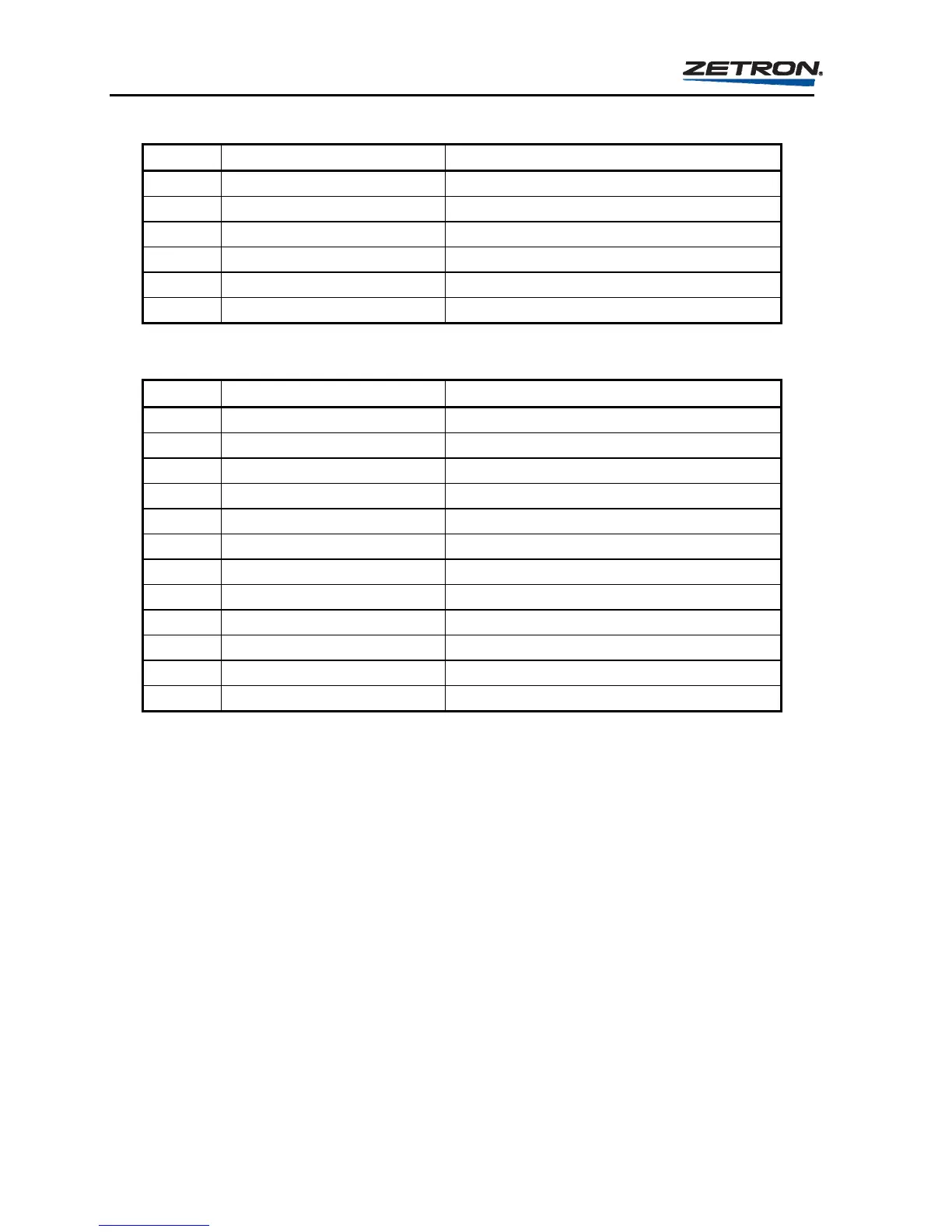
Table 10. P3 Connector Pinouts on Rear Panel of Model 25
P3 Pin Label Function
1 RELAY COM. control relay common point
2 GROUND signal ground
3 CHANNEL BUSY 4 busy input for SEND key 4
4 CHANNEL BUSY 3 busy input for SEND key 3
5 CHANNEL BUSY 2 busy input for SEND key 2
6 CHANNEL BUSY 1 busy input for SEND key 1
Table 11. P4 Connector Pinouts on Rear Panel of Model 25
P4 Pin Label Function
1 +12 VDC from power source
2 +12 VDC from power source to regulator
3 GROUND from power source
4 GROUND from power source
5 DIGITAL DATA OUTPUT for future digital Tx
6 GROUND signal ground
7 DIGITAL MODE OUTPUT for future digital Tx
8 GROUND signal ground
9 LOOP OUTPUT * to Auxiliary panels
10 GROUND signal ground
11 LOOP INPUT * from Auxiliary panels
12 CHASSIS goes to case, chassis not grounded
* Jumper “LOOP OUTPUT” to “LOOP INPUT” if no auxiliary Instant Call panels are used.
Transmitter and Console Control
The Model 25 is designed to directly control from one to eight channels or transmitters,
singly or simultaneously. The encoder achieves transmitter or console control through its
eight control relays, its single DPDT Push-To-Talk (PTT) relay and its single DPDT Audio
Steering relay. The control relays (labeled RELAY at the connection) have normally open
contacts and each one closes to a common, ungrounded point (RELAY COM.) when
activated. During a calling sequence, the PTT relay and up to eight control relays will close.
The control relays used during a calling sequence depend on the programming of the
encoder. If one of the four
SEND keys is used to initiate a calling sequence, then the control
relays used are the relays programmed for the
SEND key. If an instant call key is used to
send a call stack then, the control relays used are the relays programmed for the calls in the
call stacks. The exact timing of the relay closures may be found in the “OPERATION”
section under “THE CALLING SEQUENCE” on page 22. The details of programming the
transmitter control parameters may be found in the “PROGRAMMING ENCODER FROM
FRONT PANEL” section.