Auxiliary Panel Installation
025-9567E 53
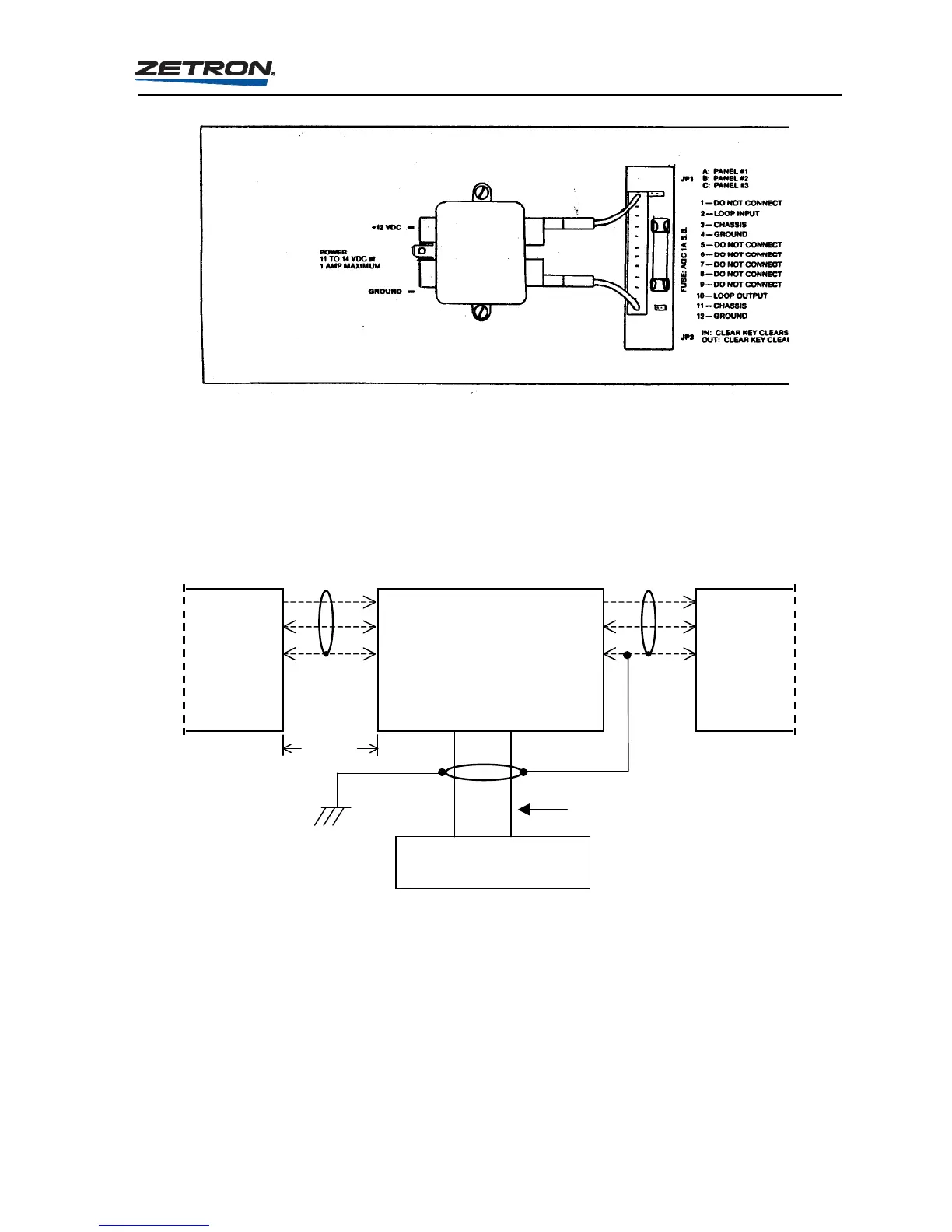
Figure 10. Power connections to Model 25 Auxiliary Panel
The power required is +11 to +14 VDC at 1 ampere maximum. The fuse visible in the back
panel cutout should be an AGC 1 ampere slow-blow.
Figure 11 shows the suggested interconnection of the auxiliary panel.
AUXILIARY PANEL
(2) Loop In
(4) Ground
(3) Chassis
Loop Out (10)
Ground (12)
Chassis (11)
Loop Out
Ground
Chassis
Loop In
Ground
Chassis
PRIOR
PANEL
NEXT
PANEL
Shield Shield
Power Source
100 feet
maximum
Earth
Ground
18 Gau
e Minimum
+12 V
DC
Ground
Figure 11. Typical Connections for Model 25 Auxiliary Panel
PANEL LABELS
The labeling of the Auxiliary panel is identical to labeling the instant call keys on the Model
25 Encoder. This is covered on page 47.