Operation
10 025-9567E
USING THE KEYPAD
Note: If desired, the keypad may be disabled by placing the keypad jumper inside the
enclosure to the “disabled” position (see “Keypad Enable/Disable” on page 34).
To enter encoding information, use the 16-key pad. As digits are accepted from the keypad,
they will appear in the display filling in at the left-hand display first. There are two displayed
characters that are somewhat cryptic in their appearance due to the seven segment displays.
The “#” character is displayed as three horizontal lines, “ ”. The “*” character is displayed
as a “degree” symbol, “ ° ”. As the display fills, new accepted digits will enter on the right-
hand display while the previous display scrolls to the left. Entries that are not acceptable will
cause an error beep and they will not appear in the display. If the encoder fails to receive
keypad input for more than 30 seconds, it will re-enter the idle state displaying either the
time or the single dash. When this happens, the previous keystrokes are lost.
The first digit entered is the block or leading digit which is used to steer the encoder to one of
up to 13 formats or the call stack. The possible format leading digits are “1” through “D”.
The leading digit for accessing call stacks is “0”. If the attempted leading digit is not
accepted it is because the block represented by the leading digit has not been assigned to an
encoding format. After initialization, the leading digits 1, 2, and 3 are accepted to allow use
of the alert feature.
After the leading digit, the remaining digits are information used by the chosen encoding
format. Digits that are not accepted by the format will cause a beep. A beep may also be
caused by attempting to enter more digits than are allowed by the chosen encoding format.
Table 1 shows the required input for each of the formats supported by the Model 25. Note
that the leading block digit “b” must be in the range 1-9, A, B, C, or D. The actual block digit
used to access the given format depends on the programming. The leading block digit “0” is
reserved for accessing the call stacks.
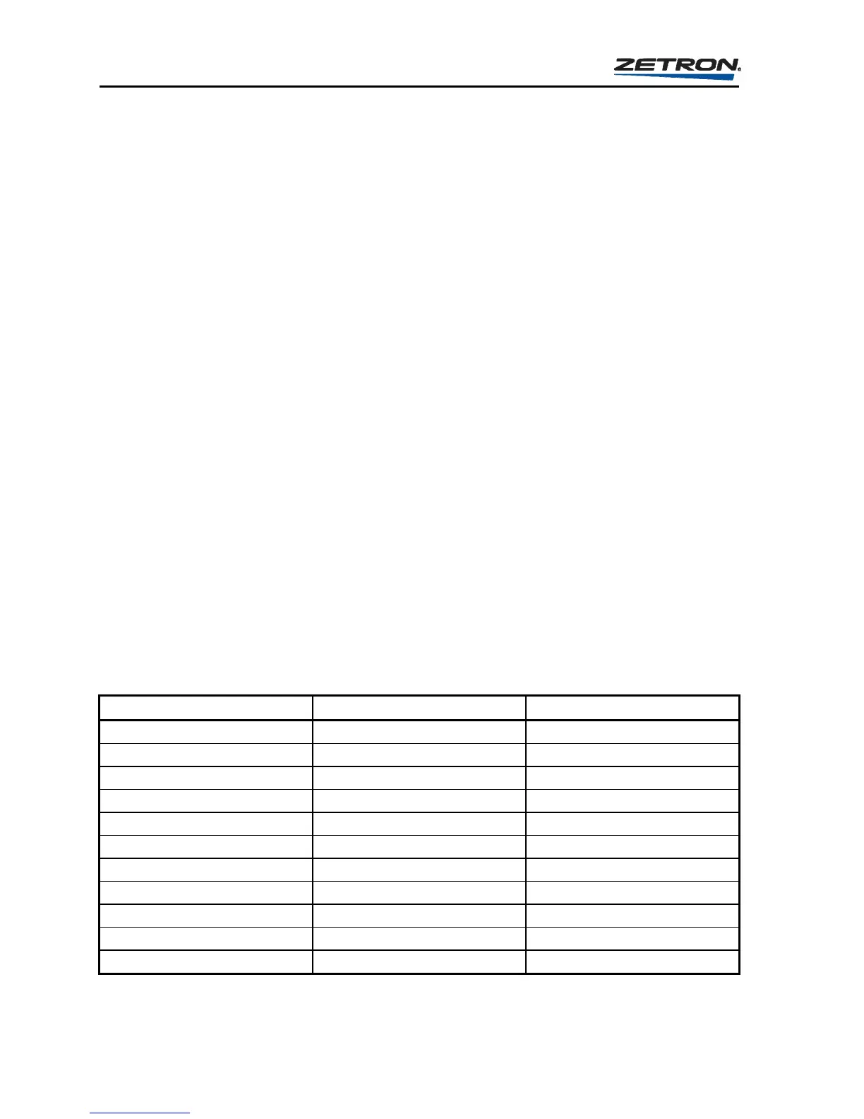
Table 1. Page Entry Requirements by Paging Format
FORMAT REQUIRED ENTRY NUMBER RESTRICTIONS
CALL STACK 0nnn nnn= 000-358
1000 CALL TWO TONE bnnn n= 0-9
CUSTOM CALL bnnn nnn= 000-195
QUICK CALL 1 (2+2) bnnnn n= 0-9, A or B
5 TONE SEQUENTIAL bnnnnn n= 0-9
6 TONE SEQUENTIAL bnnnnnn n= 0-9
STORED DTMF bn - bnnnnnnnn n= 0-9, A-D, # or *
LIVE DTMF b digits sent as entered
STORED ROTARY DIAL bn - bnnnnnnnn n= 0-9
LIVE ROTARY DIAL b digits sent as entered
AUTOMATIC ALERT bn n= 0-3