Encoder Installation
025-9567E 39
REAR PANEL CONNECTIONS
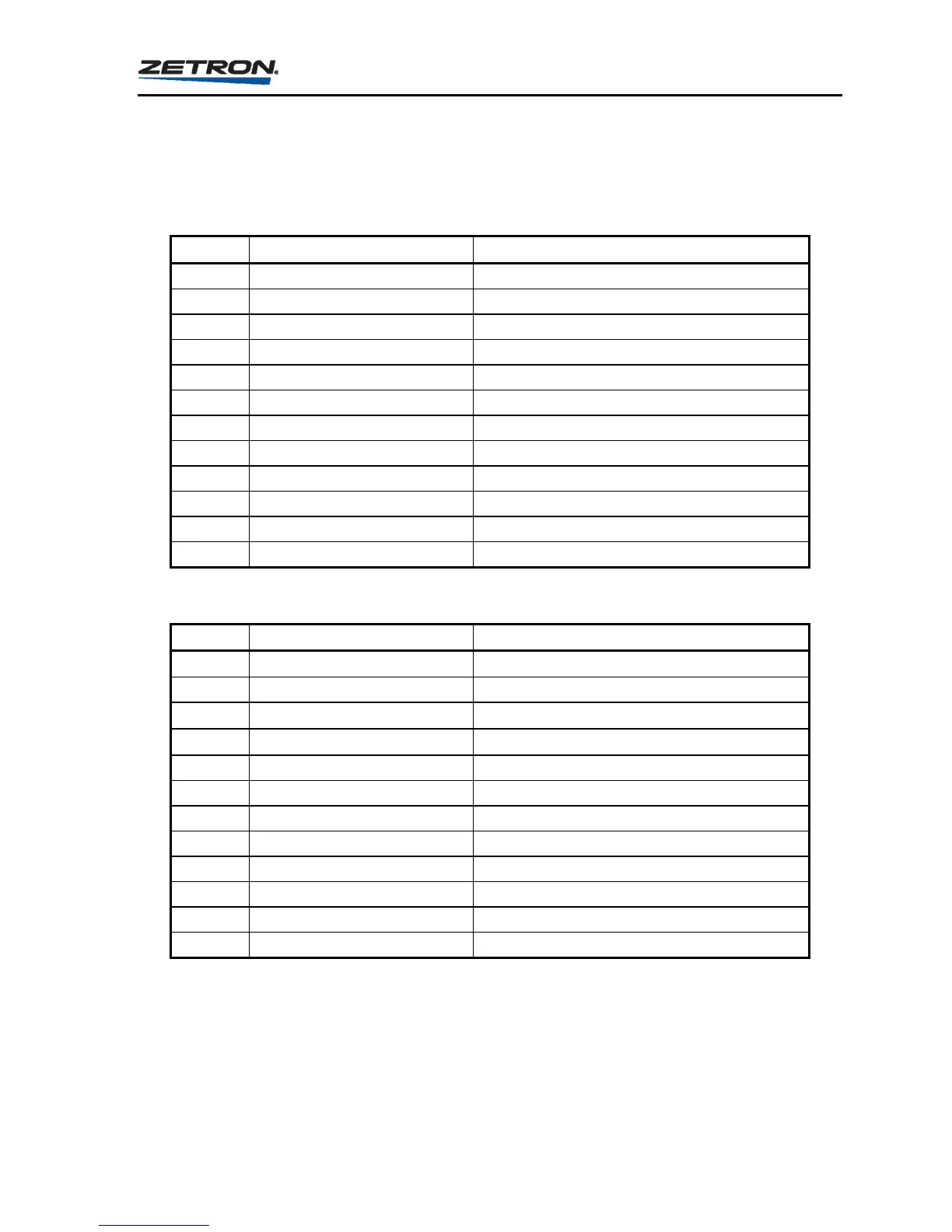
Table 8 through Table 11 list the signal connections for connectors P1 through P4 on the rear
panel of the Model 25.
Table 8. P1 Connector Pinouts on Rear of Model 25
P1 Pin Label Function
1 PTT N.O. A push-to-talk normally open
2 PTT N.C. A push-to-talk normally closed
3 PTT COM. A push-to-talk common A
4 PTT COM. B push-to-talk common B
5 PTT N.O. B push-to-talk normally open
6 PTT N.C. B push-to-talk normally closed
7 AUDIO N.O. A audio switch normally open
8 AUDIO N.C. A audio switch normally closed
9 AUDIO COM. A audio switch common A
10 AUDIO COM. B audio switch common B
11 AUDIO N.O. B audio switch normally open
12 AUDIO N.C. B audio switch normally closed
Table 9. P2 Connector Pinouts on Rear Panel of Model 25
P2 Pin Label Function
1 TONE OUTPUT 2A external monitor speaker, 4 to 8 speaker
2 TONE OUTPUT 2B external monitor speaker, 4 to 8 speaker
3 TONE OUTPUT 1A
audio tone output, 600
4 TONE OUTPUT 1B
audio tone output, 600
5 RELAY 8 8th control relay contact
6 RELAY 7 7th control relay contact
7 RELAY 6 6th control relay contact
8 RELAY 5 5th control relay contact
9 RELAY 4 4th control relay contact
10 RELAY 3 3rd control relay contact
11 RELAY 2 2nd control relay contact
12 RELAY 1 1st control relay contact