Z8
®
CPU
User Manual
UM001604-0108 Serial Input/Output
116
UART Bit-Rate Generation
When Port 3 Mode Register bit 6 is set to 1, the UART is enabled and T0 automatically
becomes the bit rate generator (see Figure 106). The end-of-count signal of T0 no longer
generates Interrupt Request IRQ4. Instead, the signal is used as the input to the divide-by-
16 counters (one each for the receiver and the transmitter) that clock the data stream.
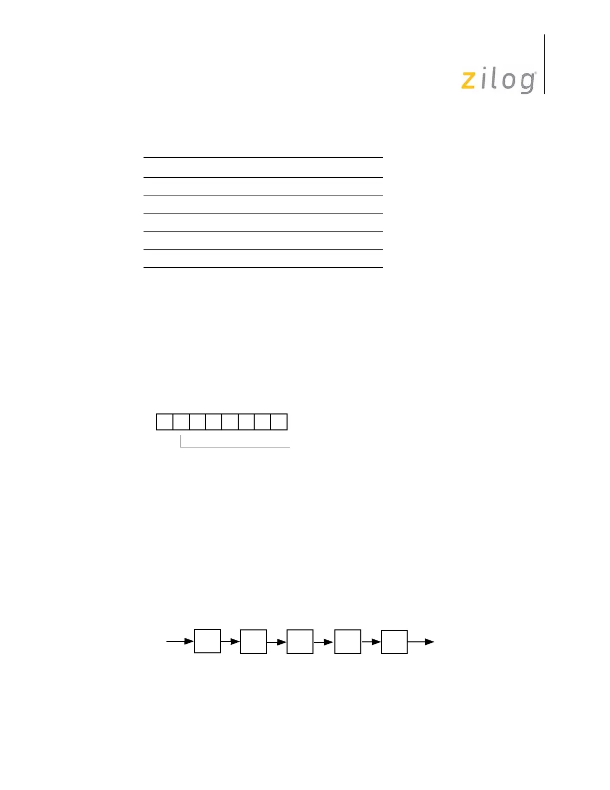
The divide chain that generates the bit rate is displayed in Figure 107. The bit rate is given
by the following equation:
Bit Rate = XTAL Frequency ÷ (2 x 4 x p x t x 16)
where p and t are the initial values in Prescaler0 and Counter/Timer0, respectively. The
final divide-by-16 is required because T0 runs at 16 times the bit rate in order to synchro-
nize on the incoming data.
Table 23. UART Register Map
Register Name Identifier Hex Address
Port 3 Mode P3M F7
T0 Prescaler PRE0 F5
Timer/Counter0 T0 F4
Timer Mode TMR F1
UART SIO F0
Figure 106. Port 3 Mode Register and Bit-Rate Generation
Figure 107. Bit Rate Divide Chain
D7 D6 D5 D4 D3 D2 D1 D0
(Write-Only)
Port 3 Mode Register (P3M)
Register F7h
0 P30 Input and P37 = Output
1 P30 Serial In and P37 = Serial Out
P
t
÷
16
Bit Rate
÷
4
÷
2
Clock
PRE0
T0
f
XTAL

 Loading...