Z8
®
CPU
User Manual
UM001604-0108 Counters and Timers
91
T1 is triggered counting continues until software resets the Enable Count bit. Interrupt
request IRQ5 is generated when T1 reaches its end-of-count.
Retriggerable Input Mode
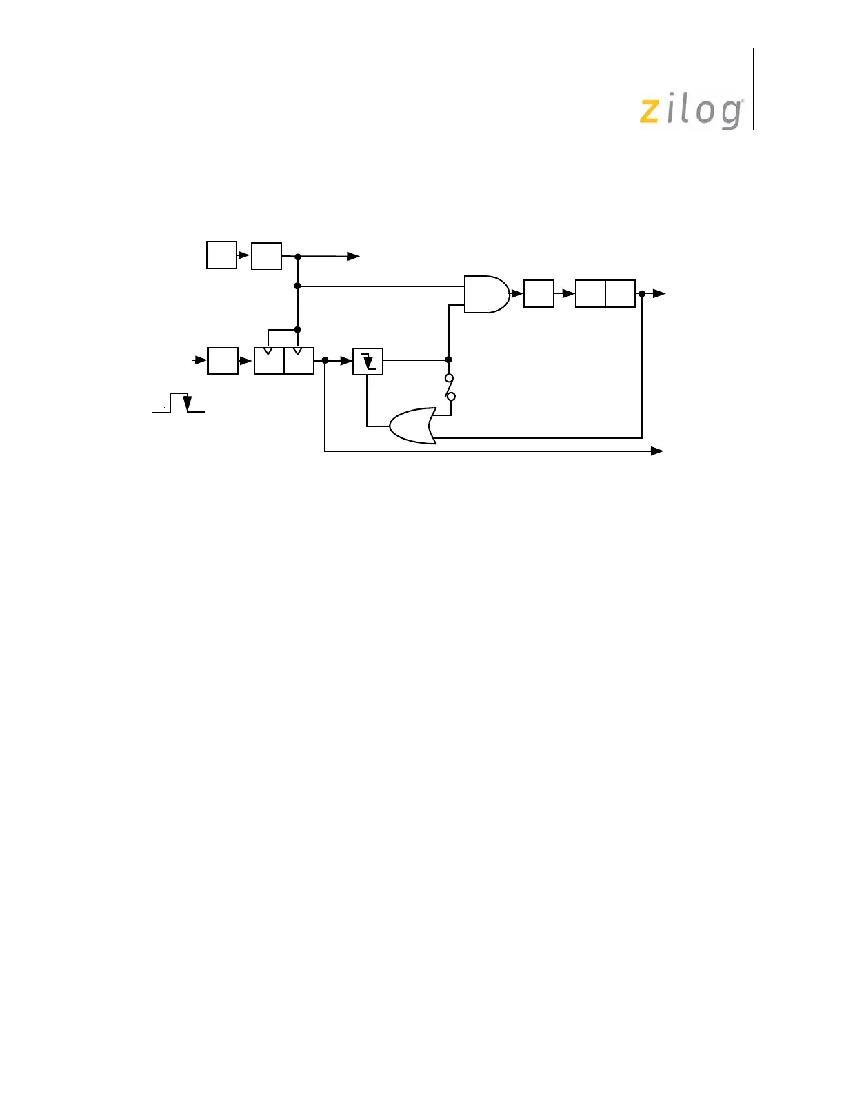
The T
IN
Retriggerable Input Mode (TMR bits 5 and 4 are set to 1) causes T1 to load and
start counting on every occurrence of a High-to-Low transition on T
IN
, see Figure 84.
Interrupt request IRQ5 is generated if the programmed time interval (determined by T1
prescaler and counter/timer register initial values) has elapsed because of the last High-to-
Low transition on T
IN
. In SINGLE-PASS Mode, the end-of-count resets the Enable Count
bit. Subsequent T
IN
transitions do not cause T1 to load and start counting until software
sets the Enable Count bit again. In Continuous Mode, counting continues once T1 is trig-
gered until software resets the Enable Count bit. When enabled, each High-to-Low T
IN
transition causes T1 to reload and restart counting. Interrupt request IRQ5 is generated on
every end-of-count.
Cascading Counter/Timers
For some applications, it may be necessary to measure a time interval greater than a single
counter/timer can measure. In this case, T
IN
and T
OUT
can be used to cascade T0 and T1
as a single unit (see Figure 85 on page 92). T0 should be configured to operate in Continu-
ous mode and to drive T
OUT
. T
IN
should be configured as an external clock input to T1
and wired back to T
OUT
. On every other T0 end-of-count, T
OUT
undergoes a High-to-Low
transition that causes T1 to count.
T1 can operate in either Single-Pass or Continuous mode. When the T1 end-of-count is
reached, interrupt request IRQ5 is generated. Interrupt requests IRQ2 (T
IN
High-to-Low
transitions) and IRQ4 (T0 end-of-count) are also generated but are most likely of no
importance in this configuration and should be disabled.
Figure 84. Triggered Clock Mode
OSC
÷
2
÷
4
D D
PRE1
TMR
P3
1
T1
IRQ
2
T
IN
IRQ
5
Trigger
D
5
–D
4 =
11
Internal
TMR
D
5 =
1
Clock
Edge
Trigger

 Loading...