Z8
®
CPU
User Manual
UM001604-0108 Counters and Timers
81
(T
IN
) using P31. Port 3 line P36 can serve as a timer output (T
OUT
) through which T0, T1,
or the internal clock can be output. The timer output toggles at the end-of-count.
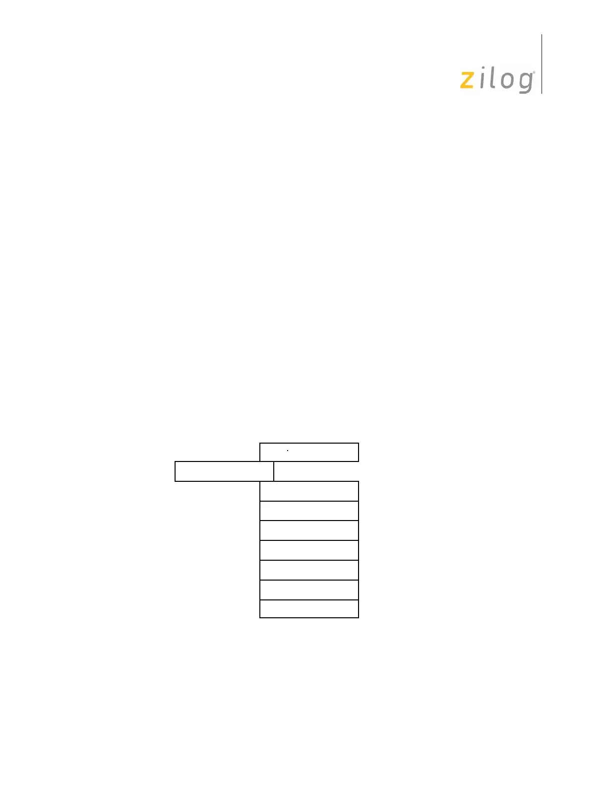
The counter/timer, prescaler, and associated mode registers are mapped into the register
file as displayed in Figure 69. This allows the software to treat the counter/timers as gen-
eral-purpose registers, and eliminates the requirement for special instructions.
Prescalers and Counter/Timers
The prescalers, PRE0 (F5h) and PRE1 (F3h), each consists of an 8-bit register and a 6-
bit down-counter as displayed in Figure 68 on page 80. The prescaler registers are write-
only registers. Reading the prescalers returns the value
FFh. Figure 70 on page 82 and
Figure 71 on page 82 displays the prescaler registers.
The six most significant bits (D2–D7) of PRE0 or PRE1 hold the prescalers count modulo,
a value from 1 to 64 decimal. The prescaler registers also contain control bits that specify
T0 and T1 counting modes. These bits also indicate whether the clock source for T
1
is
internal or external. These control bits will be discussed in detail throughout this chapter.
The counter/timer registers, T0 (
F4h) and T1 (F2h), each consists of an 8-bit down-
counter, a write-only register that holds the initial count value, and a read-only register
that holds the current count value (see Figure 68 on page 80). The initial value can range
from 1 to 256 decimal (
01h,02h,..,00h). Figure 72 on page 83 displays the counter/timer
registers.
Figure 69. Counter/Timer Register Map
HEX Identifiers
T0 Prescaler
F7
Timer/Counter0
Port 3 Mode
T1 Prescaler
Time/Counter1
Timer Mode
F5
F4
F3
F2
F1
DEC
247
245
244
243
242
241

 Loading...